
Rough channel microfluidic devices

a microfluidic device and microfluidic technology, applied in the field of microfluidic devices in the rough channel, can solve the problems of undesirable fluid flow behavior, large amount of reagents and analytes used, and high cost of reagents, so as to achieve less susceptibleness and more predictable

Inactive Publication Date: 2007-06-21
KIMBERLY-CLARK WORLDWIDE INC
View PDF3 Cites 2 Cited by
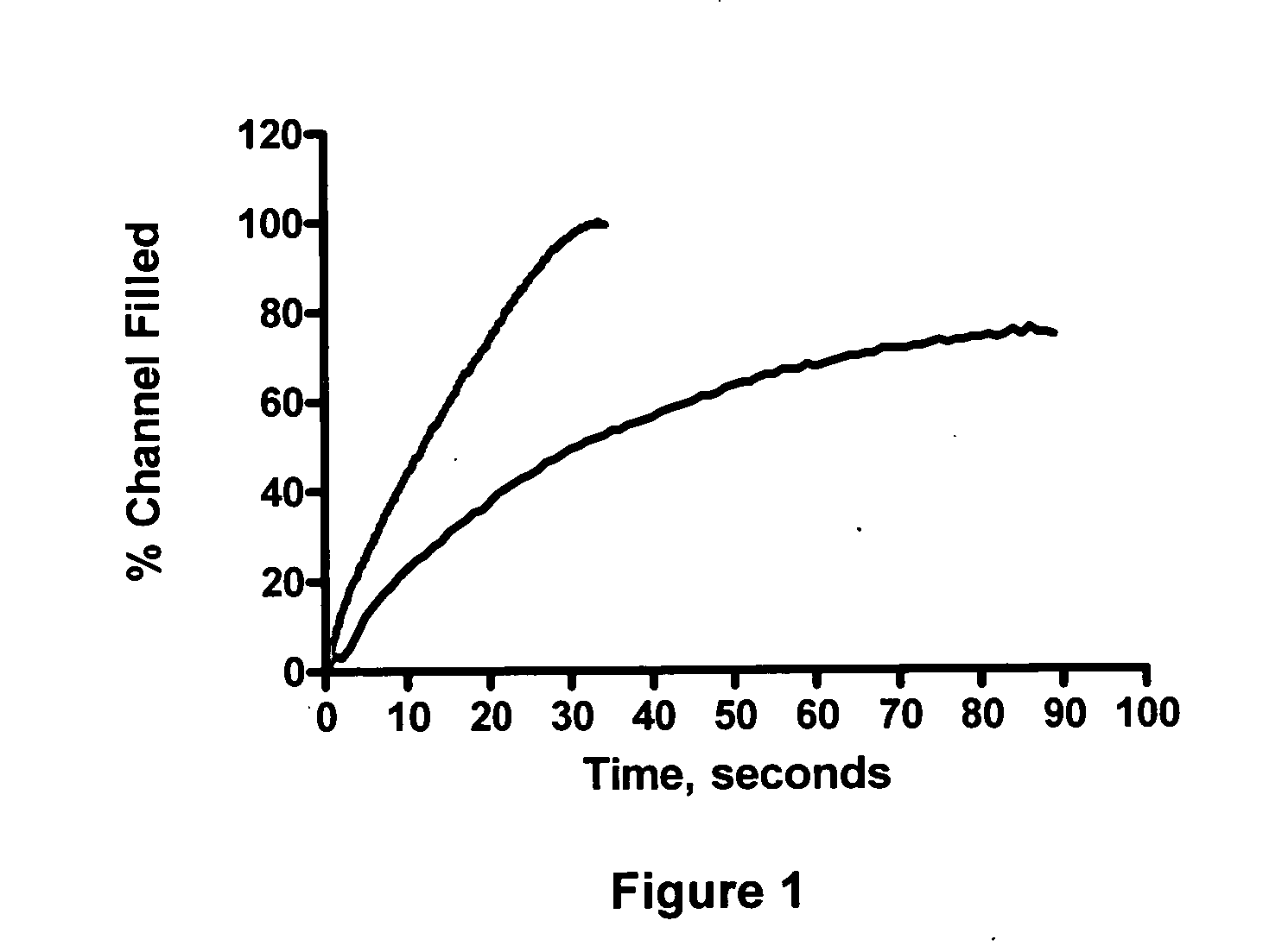
  • Summary
  • Abstract
  • Description
  • Claims
  • Application Information

AI Technical Summary

Benefits of technology

[0005] The inventors have found that if the internal surfaces of a micro-fluidic channel are roughened, the advancing air-liquid interface is presented with a continuously varying and random contact angle, assuming the scale of roughness is small with respect to the dimensions of the channel. This results in a flow behavior that is much less susceptible to variances in the surface energy of the channel walls and is therefore more predictable.
[0006] In addition to greater flow surge consistency, microchannels with roughened wall surfaces can provide quicker fill times due to the enhanced wettability of rough surfaces as well as provide increased surface area for particulate or cell capture.

Problems solved by technology

First, because the volume of fluids within these channels is very small, usually several nanoliters, the amount of reagents and analytes used is also very small.
This is especially significant for expensive reagents.
Any surface energy variances on the internal walls of the microfluidic channel(s) can result in unpredictable and undesirable fluid flow behavior.
This issue can often create unreasonable specifications for manufacturing of microfluidics.

Method used


Image

  • Rough channel microfluidic devices

Examples


Embodiment Construction

[0009] As used herein the term “microfluidic” refers to devices having channels that have one dimension less than 1 mm in size, more particularly they have channels having one dimension in the range of 100 microns or less, and for the detection of viruses, they have channels having one dimension in the range of 10 microns or less.

[0010] The flow of a fluid through a microfluidic channel can be characterized by the Reynolds number, defined as Re=LVavgρ / μ (equation1), where L is the most relevant length scale, μ is the viscosity, ρ is the fluid density, and Vavg is the average velocity of the flow. For many microchannels, L is equal to 4A / P where A is the cross sectional area of the channel and P is the wetted perimeter of the channel. Due to the small dimensions of microchannels, the Re is usually much less than 100, often less than 1.0. In this Reynolds number regime, flow is completely laminar and no turbulence occurs. The transition to turbulent flow generally occurs in the range...


PUM


Abstract

There is provided a rough microfluidic channel for use, for example, in a lateral flow assay device. The rough microfluidic channel has a roughness greater than a similar channel that is smooth, as measured by a Reynolds number for flow under otherwise identical conditions, which is at least 50 percent greater than the Reynolds number for the smooth channel. Alternatively, the roughness may be greater than a similar channel that is smooth, as measured by the fill time which is at least 25 percent lower for said rough channel than said smooth channel.

Description

BACKGROUND OF THE INVENTION [0001] Microfluidic devices can be used to obtain a variety of interesting measurements including molecular diffusion coefficients, fluid viscosity, pH, chemical binding coefficients and enzyme reaction kinetics. Other applications for microfluidic devices include capillary electrophoresis, isoelectric focusing, immunoassays, flow cytometry, sample injection of proteins for analysis via mass spectrometry, PCR amplification, DNA analysis, cell manipulation, cell separation, cell patterning and chemical gradient formation. Many of these applications have utility for clinical diagnostics. [0002] A microfluidic device characteristically has one or more channels with at least one dimension less than 1 mm. Common fluids used in microfluidic devices include whole blood samples, bacterial cell suspensions, protein or antibody solutions and various buffers. The use of microfluidic devices to conduct biomedical research and create clinically useful technologies has...

Claims


Application Information

Patent Timeline
IPC IPC(8): B01L3/02
CPCB01L3/502746B01L2300/0825B01L2300/166B01L2400/086G01N33/558F15D1/06B01L3/00G01N33/54388
Inventor COHEN, DAVID S.FEASTER, SHAWN R.
Owner KIMBERLY-CLARK WORLDWIDE INC
Learn More