Image encoding method, and image decoding method
a technology of image encoding and decoding method, which is applied in the direction of color television with bandwidth reduction, signal generator with optical-mechanical scanning, and signal system with bandwidth reduction. it can solve the problems of loss of high-frequency components of images originally encoding, and achieve significant practical value, improve image quality, and increase the effect of encoding amoun
- Summary
- Abstract
- Description
- Claims
- Application Information
AI Technical Summary
Benefits of technology
Problems solved by technology
Method used
Image

Examples
first embodiment
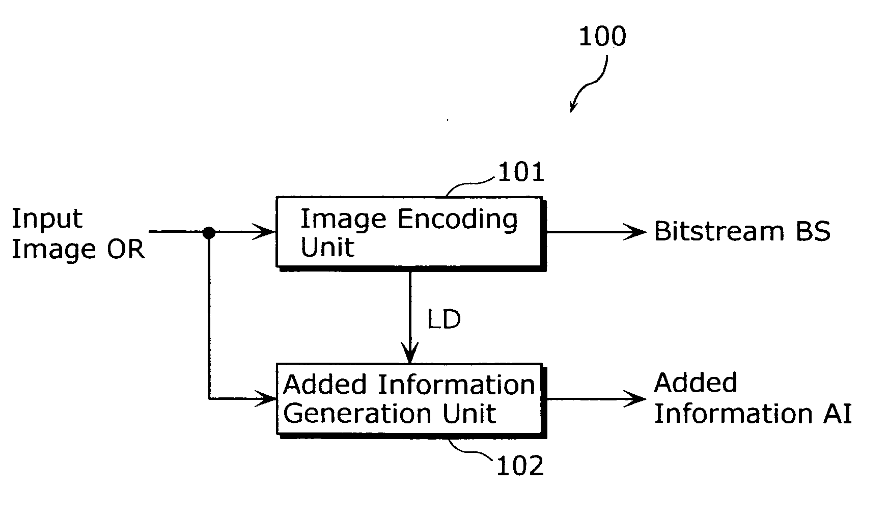
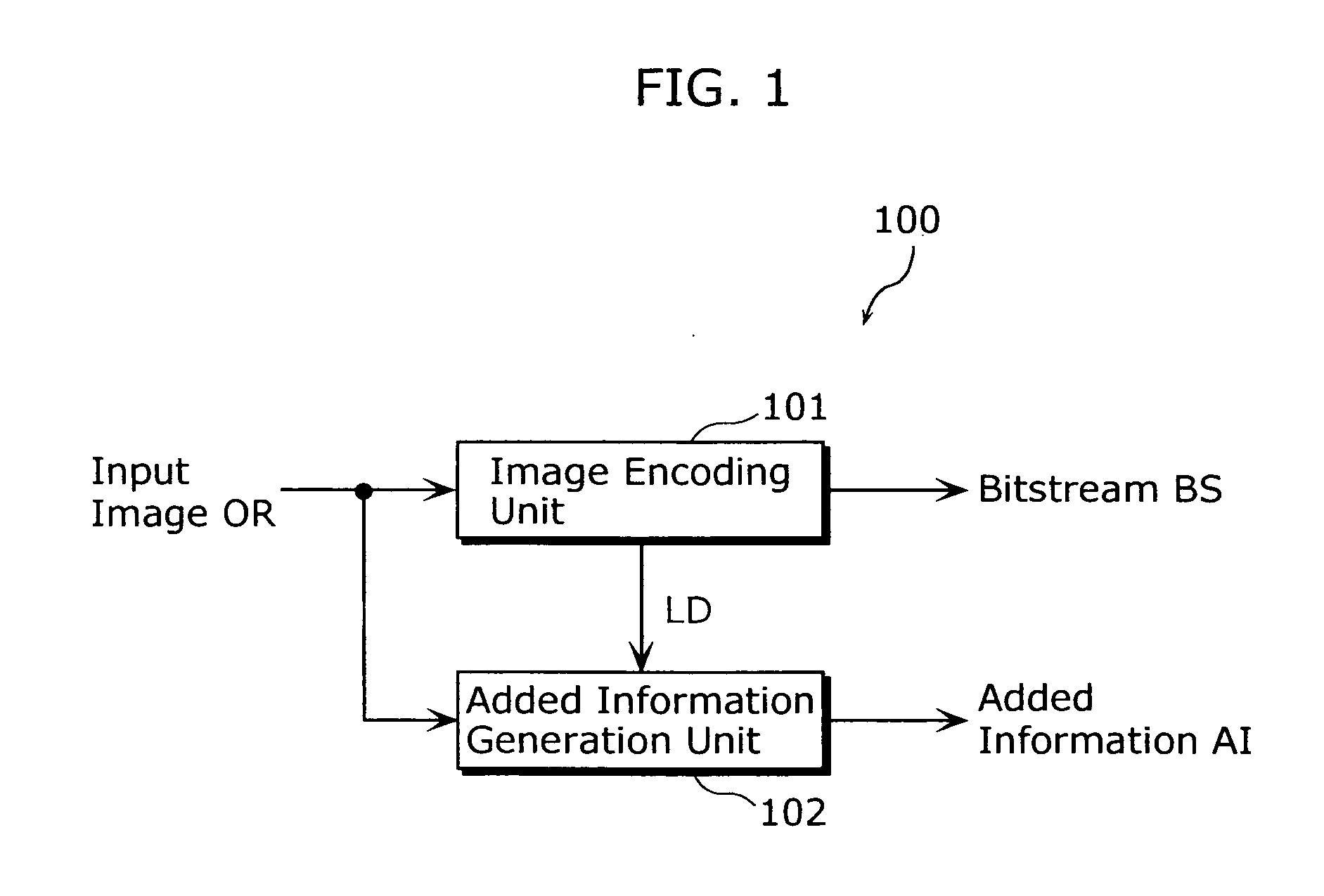
[0039]FIG. 1 is a block diagram showing a configuration of an image encoding apparatus 100 that uses an image encoding method according to the present invention. As shown in FIG. 1, the image encoding apparatus 100 includes an image encoding unit 101 and an additional information generation unit 102.
[0040] An input image OR is inputted into the image encoding unit 101. The image encoding unit 101 executes a conventional image encoding method. It is possible to use the ISO / IEC standard Joint Photographic Experts Group (JPEG) format, Moving Picture Experts Group (MPEG) format, the ITU-T standard H.26x format, or the like as the conventional image encoding method. The image encoding unit 101 outputs bitstream BS obtained by encoding the input image OR and a decoded image LD. The bitstream BS is outputted to the exterior of the image encoding apparatus 100, and is transmitted, stored, or processed in another such manner.
[0041] The decoded image LD is inputted into the additional infor...
second embodiment
[0092]FIG. 11 is a block diagram showing a configuration of an image decoding apparatus 1200 used in an image decoding method according to the present invention. As shown in FIG. 11, the image decoding apparatus 1200 includes an image decoding unit 1201 and an additional information processing unit 1202. The bitstream BS and additional information AI, which are generated by an image encoding apparatus that uses an image encoding method according to the present invention as described in the first embodiment, are inputted into the image decoding unit 1200.
[0093] The bitstream BS is inputted into the image decoding unit 1201. The image decoding unit 1201 performs conventional image decoding on the bitstream BS. For example, in the case where the bitstream BS is encoded in the JPEG format, it is decoded in the JPEG format; in the case where the bitstream BS is encoded in the MPEG format, it is decoded in the MPEG format; in the case where the bitstream BS is encoded in the H.26x format...
third embodiment
[0111] Furthermore, by storing a program for realizing an image encoding method and image decoding method such as described in each of the above embodiments in a storage medium such as a flexible disk, the processing described in each of the above embodiments can easily be executed by an independent computer system.
[0112]FIGS. 15A, 15B, and 15C are descriptive diagrams showing the case where the image encoding method and the image decoding method as described in each of the above embodiments are executed by a the computer system, using the program stored on the storage medium such as a flexible disk.
[0113]FIG. 15B shows the exterior of the flexible disk as viewed from the front, a cross-section construction, and the flexible disk, while FIG. 15A shows an example of a physical format of the flexible disk, which is the storage medium itself. A flexible disk FD is contained within a case F, and plural tracks are formed on a surface of the disk, running concentrically from an outer pe...
PUM
 Abstract
Description
Claims
Application Information
 - R&D
- Intellectual Property
- Life Sciences
- Materials
- Tech Scout
- Unparalleled Data Quality
- Higher Quality Content
- 60% Fewer Hallucinations
Browse by: Latest US Patents, China's latest patents, Technical Efficacy Thesaurus, Application Domain, Technology Topic, Popular Technical Reports.
© 2025 PatSnap. All rights reserved.Legal|Privacy policy|Modern Slavery Act Transparency Statement|Sitemap|About US| Contact US: help@patsnap.com