
Apparatus for converting transmission structure

a transmission structure and apparatus technology, applied in electrical apparatuses, multiple-port networks, coupling devices, etc., can solve the problems of interference with the radiating electro-magnetic field of the antenna, high noise, and high dc power consumption

Inactive Publication Date: 2007-06-21
SAMSUNG ELECTRONICS CO LTD
View PDF3 Cites 7 Cited by
  • Summary
  • Abstract
  • Description
  • Claims
  • Application Information

AI Technical Summary

Benefits of technology

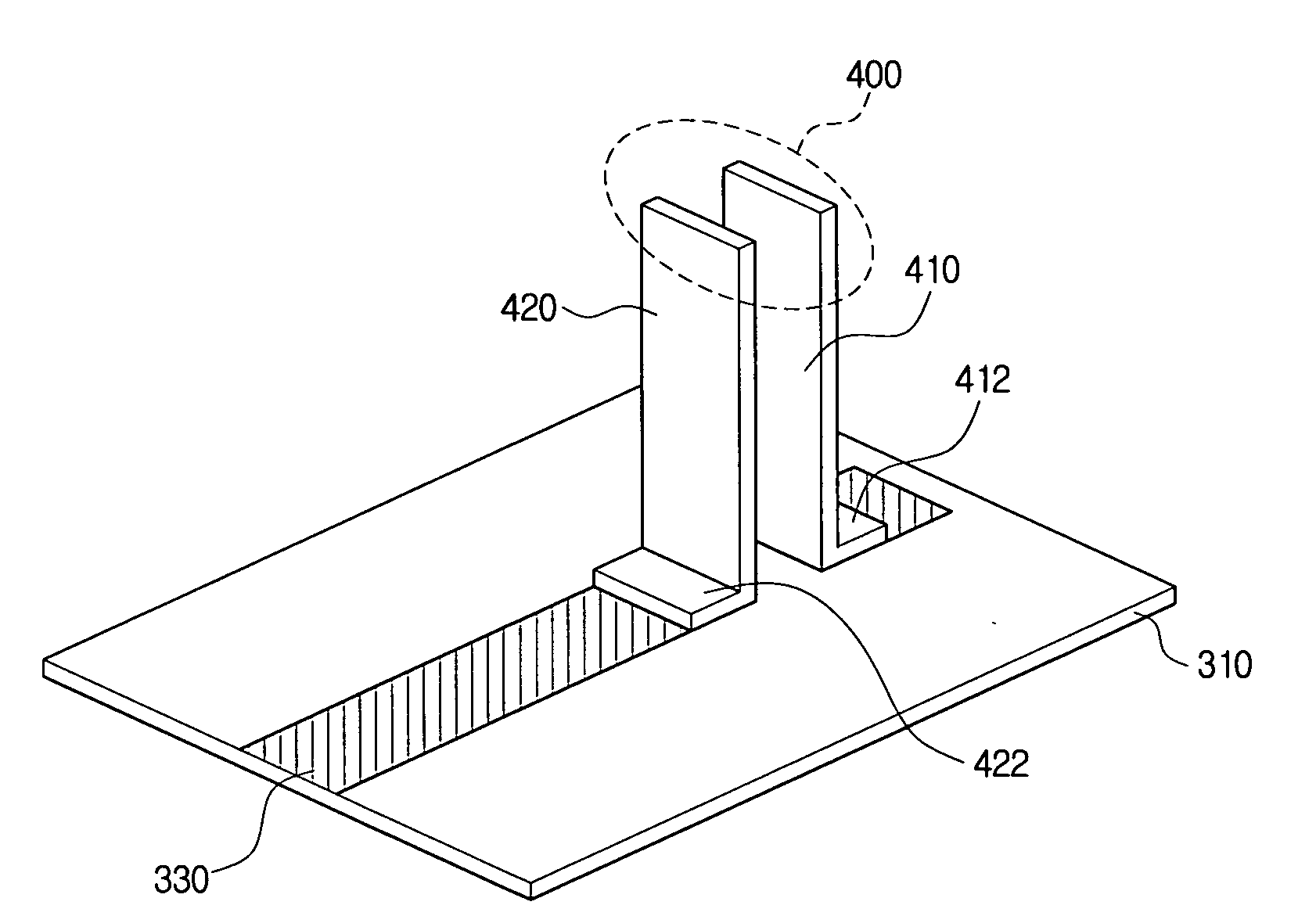
The present invention provides an apparatus for converting transmission structures, which allows for the conversion of a board-type transmission line with a ground side to a perpendicular direction and both sides of the ground side to be electro-magnetically separated. This is achieved by using a conductor-backed coplanar waveguide (CBCPW) transmission line and a plurality of via holes formed on the first ground line, proximate to the pattern line, which are connected to a parallel transmission line forming a second signal line and a second ground line parallel with the second signal line. The parallel transmission line may also comprise a strip configuration or a fixing pad extended from one end in a horizontal direction with respect to the board. The technical effects of the invention include improved signal quality, reduced interference, and improved transmission efficiency.

Problems solved by technology

Because the active balun usually has drawbacks such as high DC power consumption and high noise, passive baluns are more popularly used.
However, because the CPW transmission line emits electro-magnetic fields not only in the board, but also in the air of the upper and lower parts of the board, there always exists a possibility that the high frequency circuit on the board causes interference with the radiating electro-magnetic field of the antenna.

Method used


Image

  • Apparatus for converting transmission structure
  • Apparatus for converting transmission structure
  • Apparatus for converting transmission structure

Examples


Embodiment Construction

[0036]Hereinafter, the exemplary embodiments of the present invention will be described in detail with reference to the drawings.

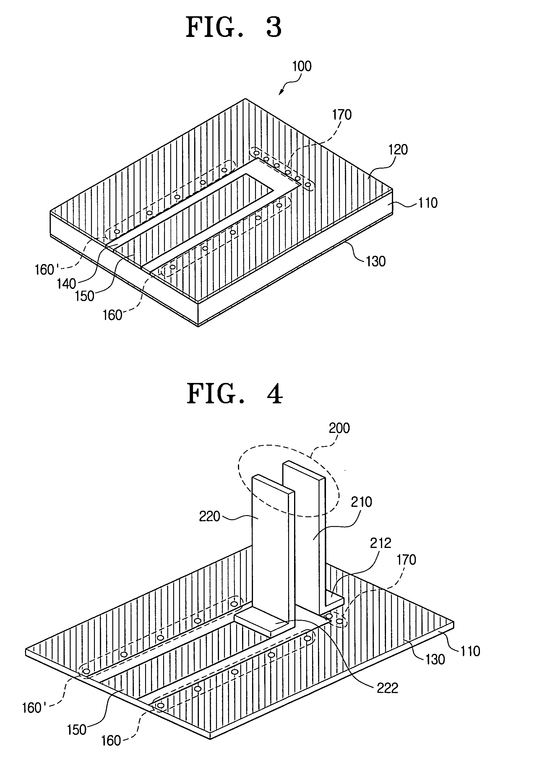
[0037]FIG. 3 shows a conductor-backed coplanar waveguide (CBCPW) transmission line according to an exemplary embodiment of the present invention.

[0038]The CBCPW transmission line 100 has the same upper structure as the coplanar waveguide transmission line, but is different that it has a ground surface 130 also on the lower part 110 of the board.

[0039]A CBCPW transmission line 100 according to an exemplary embodiment of the present invention has metal layers on the upper and lower sides of the board 110. The metal layer on one side of the board 110 forms a first ground line 120 and a first signal line 150, while the metal layer on the other side of the board 110 forms a ground surface 130. The metal layer may be formed by a copper coating.

[0040]A predetermined pattern line 140 is provided, and the metal layer of one side of the board 110 is removed in order...


PUM


Abstract

An apparatus for converting a transmission structure includes a conductor-backed coplanar waveguide (CBCPW) transmission line comprising metal layers formed on both sides of a board, a first signal line and a first ground line formed by removing the metal layer on one side of the board according to a pattern line, a plurality of via holes formed on the first ground line, proximate to the pattern line, and a parallel transmission line which forms a second signal line and a second ground line parallel with the second signal line, by being connected at one end with the first signal line and the first ground line in a substantially perpendicular direction with respect to the board, respectively. By the parallel transmission line which is connected with the planar transmission line in a perpendicular direction, a compact-sized wideband converter can be provided at an economical price.

Description

CROSS-REFERENCE TO RELATED APPLICATION[0001]This application claims priority from Korean Patent Application No. 2005-125546, filed Dec. 19, 2005, in the Korean Intellectual Property Office, the entire contents of which are incorporated herein by reference.BACKGROUND OF THE INVENTION[0002]1. Field of the Invention[0003]The present invention relates to an apparatus for converting transmission structure. More particularly, the present invention relates to an apparatus for converting transmission structure by changing a vertical feed to a horizontal feed of the board in a wideband operation.[0004]2. Description of the Related Art[0005]A balun converts signals between unbalanced signals and balanced signals, and is mainly used in devices such as balanced mixers, balanced amplifiers, phase shifters, antenna feeds and antenna connectors and low noise amplifiers.[0006]Baluns are generally categorized as active baluns and passive baluns. The active balun uses elements, while the passive balu...

Claims


Application Information

Patent Timeline
Patent Type & Authority Applications(United States)
IPC IPC(8): H01P5/02
CPCH01P5/10H01P5/08
Inventor KWON, DO-HOONKIM, YOUNG-EIL
Owner SAMSUNG ELECTRONICS CO LTD
Learn More