
Building system, beam element, column and method

a building system and beam technology, applied in the direction of structural elements, building components, load-supporting elements, etc., can solve the problems of limited degree of flexibility, limited strength of reinforcements, and labor-intensive retrofitting or modifying lines, so as to increase the strength of reinforcements, reduce labor intensity, and reduce labor intensity

Inactive Publication Date: 2007-06-21
BARTOLI
View PDF26 Cites 11 Cited by
  • Summary
  • Abstract
  • Description
  • Claims
  • Application Information

AI Technical Summary

Benefits of technology

[0009] It is an object of the present invention to provide a system of building elements in which lines, and modifications thereto, can be fitted relatively simply.
[0011] As a result of the system according to the invention, lines can be fitted and removed more easily. As the building elements are partially hollow, the lines remain accessible after the building works have been completed, so that making modifications retrospectively is less disruptive since breaking and cutting is deviated.
[0016] If only one weld seam is used, a rod may bend or hinge about the weld seam and may even break away. By using two weld seams, preferably opposite one another on a supporting element when viewed head on, the welds cannot act as a pivot and, at the same time, a stronger connection is achieved. Simultaneous welding of the two seams prevents the supporting element from becoming warped during welding. Simultaneous welding is preferably carried out using a welding robot, which not only welds simultaneously, but also for an equal period and over an equal length of every weld seam. In this manner, identical and strong welded joints are produced which generate as little tension as possible in the rods.
[0024] Preferably, the bottom part is a first slab. The top part is preferably a second slab which is arranged parallel to the bottom part. The first and second slabs are separated from one another by the reinforcement for assimilating transverse forces in the hollow space. The reinforcement can assimilate transverse forces in the hollow space, because the reinforcement comprises straight supporting elements which are connected to the rods by means of a double weld (power weld). As a result of the solid construction of the reinforcement, the latter is able to absorb forces, thus making the creation of the hollow space between the bottom and top parts possible. The hollow space may even be shaped in such a way that the concrete bottom and top parts are partially separated from one another by just the supporting elements, which are partially free of concrete. The beam element according to the invention is for example capable of spanning a width of at least 20 m and at the same time supporting a load of around 35 kg / m2.
[0029] The load-bearing capacity of the reinforcing structure is such that the hollow space in the building elements does not have to be filled with any other material in order to achieve sufficient load-bearing capacity. Thus, any lines in the hollow spaces can be moved, replaced, repaired or added. Likewise, it is possible to add additional connections to lines which have already been installed.
[0030] The above described building elements are rigid and have a large load-bearing capacity. The metal used for the reinforcement is preferably steel and in particular reinforcing steel. Furthermore, it is preferable for the supporting elements and / or the rods to be tubular, thereby further increasing the strength of the reinforcement. Solid supporting elements are feasible too.

Problems solved by technology

However, the disadvantage of the system is that, like with other buildings having solid walls and floors, fitting or modifying lines retrospectively is labour intensive.
In the present day and age, where communication means change quickly and the demand for the supply of (electrical) energy is growing constantly, this limited degree of flexibility is a major drawback.
Thus the strength of the reinforcement is limited.
However, fitting the system ceiling is labour intensive as the lines and the system ceiling have to be fitted to the floor.
Furthermore, the above-mentioned drawbacks with regard to lines having to be led through the floor remain, as cutting, drilling and the like are necessary.

Method used


Image

  • Building system, beam element, column and method
  • Building system, beam element, column and method
  • Building system, beam element, column and method

Examples


Embodiment Construction

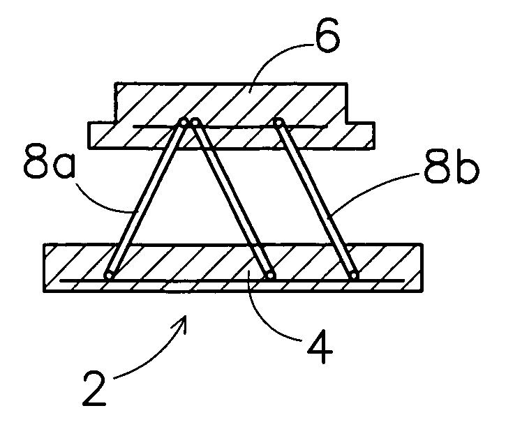
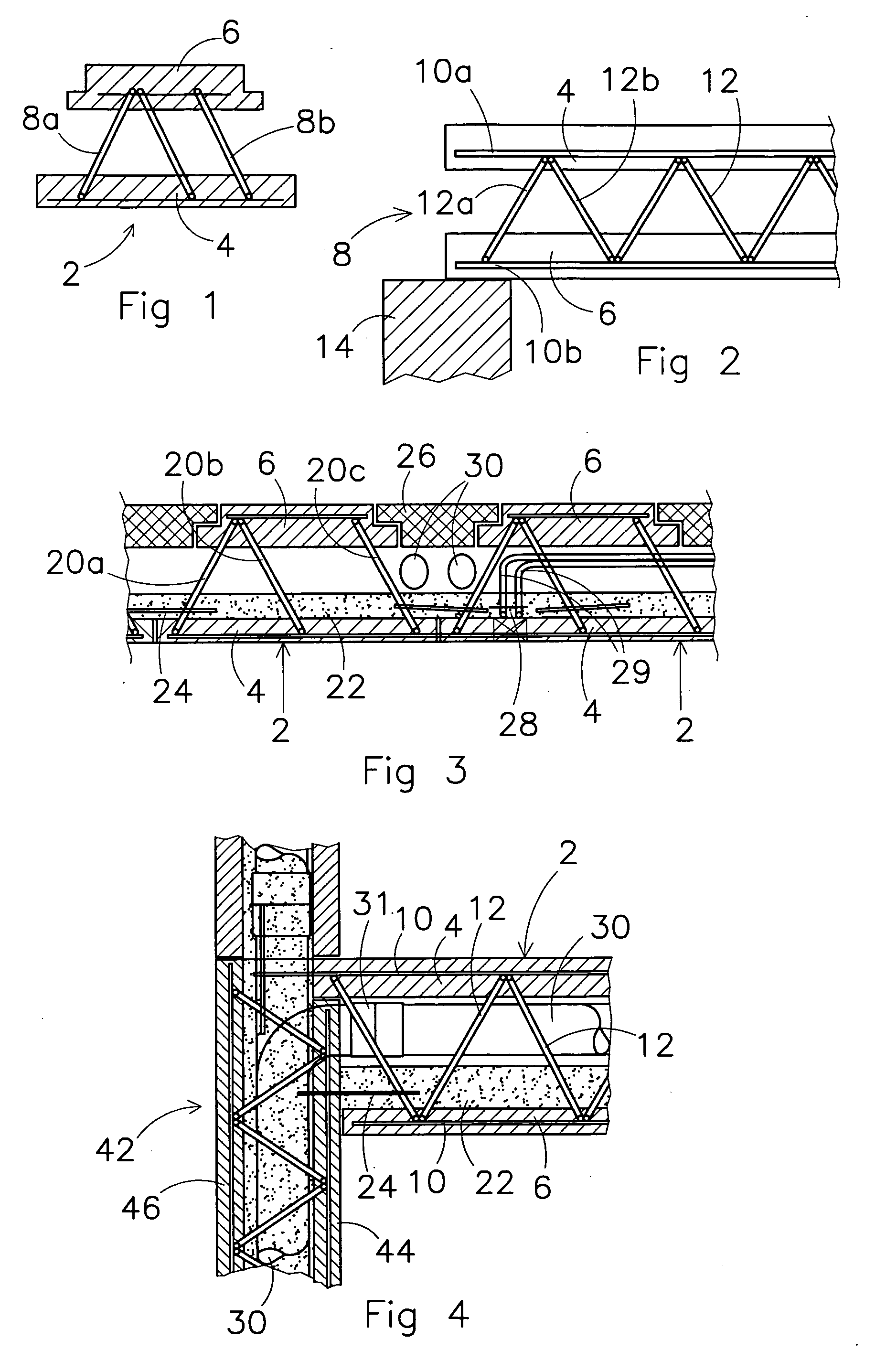
[0059]FIG. 1 shows a building element 2 which comprises a first concrete slab 4 and a second concrete slab 6. Along a part of the length of the concrete slab, the second concrete slab 6 has a smaller width than the first concrete slab 4, the width being in the plane of the paper. The length of the first concrete slab 4 may be equal to the length of the second concrete slab 6 or one of the two lengths may be less than the length of the other slab, depending on the application and the chosen design. A metal load-bearing structure is arranged between the first and the second concrete slab 4, 6. The building element comprises a first supporting element 8a and a second supporting element 8b. The supporting elements 8a and 8b are at an angle with respect to one another for the purpose of structural rigidity and strength.

[0060] If desired, a building element 2 may comprise more supporting elements, for example depending on the desired width of the building element 2, a minimum weight to b...


PUM


Abstract

The present invention provides a building system, including at least partially hollow building elements, in which hollow spaces of the building elements connect to one another for the passage of lines. The hollow spaces are accessible and remain accessible via openings in the building elements for fitting or removing the lines. The building elements include a beam element, a column, a wall element and / or a floor element. A reinforcement arranged inside the building elements comprises parallel rods, to which supporting elements are attached by at least one a double weld.

Description

CROSS-REFERENCE TO RELATED APPLICATIONS [0001] This application claims the benefit of European Application No. EP 05077675.6, filed Nov. 28, 2005, the contents of which is incorporated by reference herein. FIELD OF THE INVENTION [0002] The present invention relates to a building system, to a beam element, a column and to a method for constructing a building using a system of this type. [0003] The building system may comprise all structural components for constructing a building. The system, a building element and / or the method is, for example, used in the construction of houses as well as offices and commercial properties. BACKGROUND OF THE INVENTION [0004] U.S. Pat. No. 4,261,150 discloses a system of wall elements. The elements comprise two parallel concrete slabs which are arranged parallel to one another with an intermediate space in between and are connected to one another by a reinforcement. During building, the wall elements are provided with a support from the outside. Once ...

Claims


Application Information

Patent Timeline
IPC IPC(8): E04C3/02
CPCE04B5/04E04B5/23E04B5/38E04B5/43E04B5/48E04C2/044E04C2/34E04C3/293E04C3/34E04C2002/048
Inventor BARTELS, MICHAEL JACOBUS GERHARDUS
Owner BARTOLI
Learn More