
Sign and method for lighting

a technology of signs and methods, applied in the field of signs, can solve the problems of inconvenient use, inconvenient use, and inconvenient use of lighting devices, and achieve the effect of excellent color rendering and contras

Active Publication Date: 2007-06-21
IDEAL IND LIGHTING LLC
View PDF14 Cites 186 Cited by
  • Summary
  • Abstract
  • Description
  • Claims
  • Application Information

AI Technical Summary

Benefits of technology

[0024] In one aspect of the present invention, there is provided a sign which comprises a display having one or more color hues, and a plurality of sources of visible light for illuminating the display, the sources of visible light being selected from among solid state light emitters and luminescent materials and providing excellent color rendering and contrast for the sign.
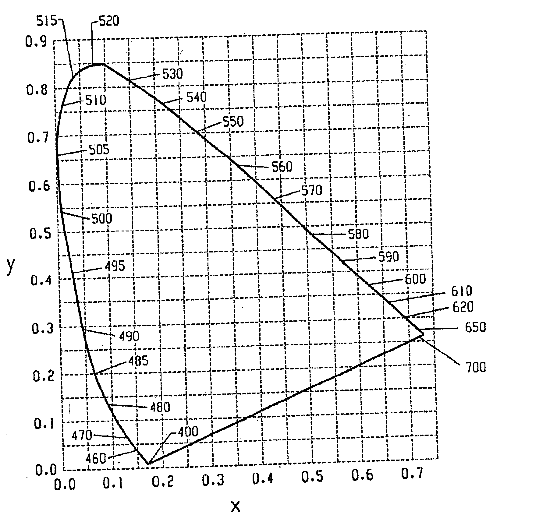
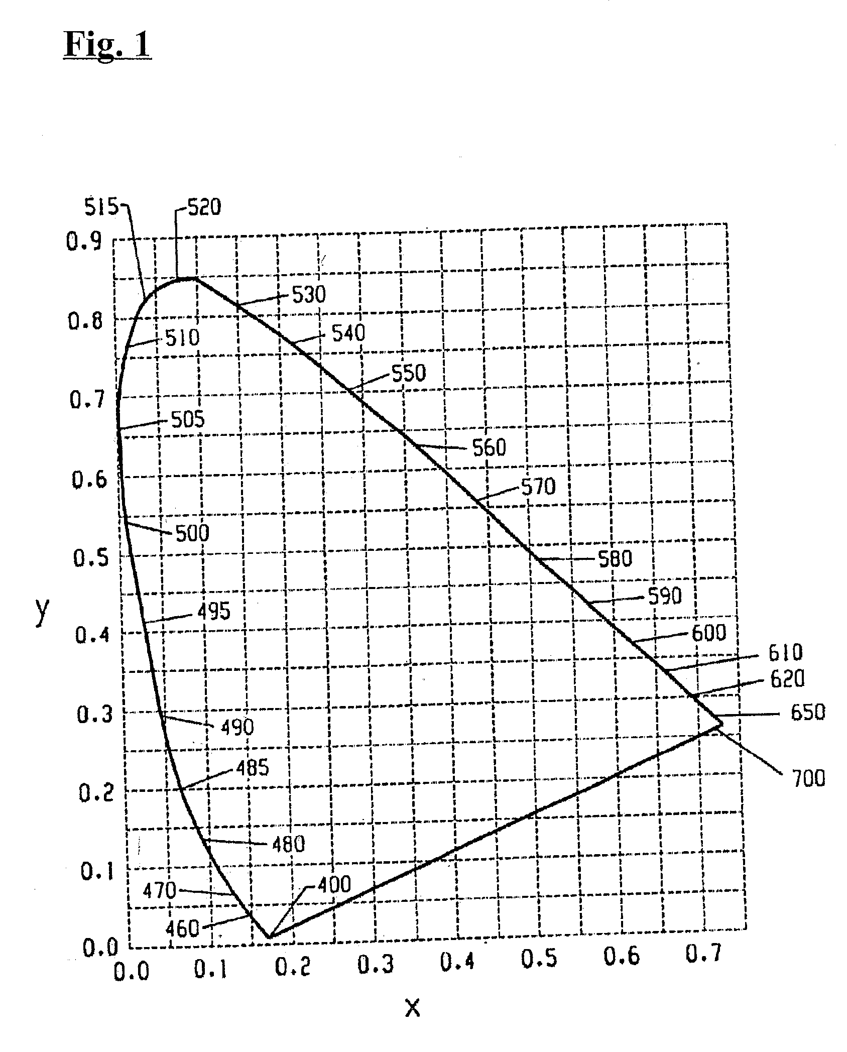
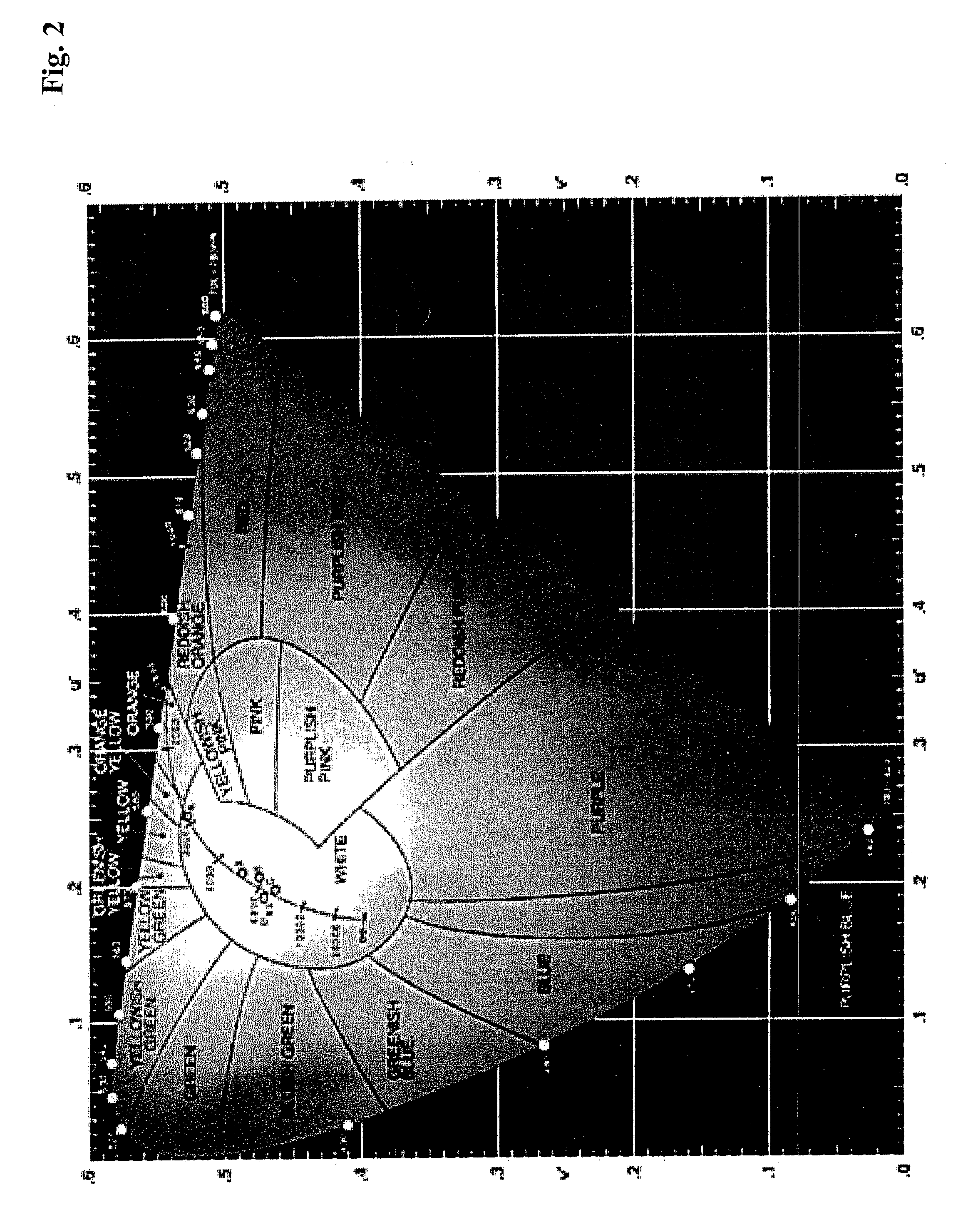
[0026] Preferably, in this aspect of the present invention, the sign includes sources of visible light which emit light having respective x,y coordinates on the 1931 CIE Chromaticity Diagram, the respective x,y coordinates, when connected by line segments, defining a shape which encompasses the respective x,y coordinates for each of the color hues on the display, whereby all of the color hues on the display can be illuminated effectively.
[0044] There is therefore a need for a high efficiency solid-state white light source that combines the efficiency and long life of white LEDs with an acceptable color temperature and good color rendering index, good contrast and a wide gamut.
[0048] As noted above, one aspect of the present invention involves the use of LEDs having an illumination surface of limited size. Additionally, where there are more emitters per unit area, these light emitters can be manufactured at a reduced cost. For example, with LEDs which are ˜ 1 / 9 the area (or so) of power LEDs with respect to the “chip / dice” size, the impact of defects greatly affects the yield (and hence the cost) of the fabricated wafer upon which the discrete LEDs are manufactured. For example, the table below shows the influence of “killer defects” on the LED yield. KillerStandardPower ChipDefectLEDLEDLoss (%)Yield (%)Yield (%)10909793375954539759298219991 A “killer defect” is defined as any defect that renders that “useable area” dead. Hence, it now is obvious that even a small number of defects can vastly increase the cost of the LED dice component.

Problems solved by technology

It is well-known that incandescent light bulbs are very energy-inefficient light sources—about ninety percent of the electricity they consume is released as heat rather than light.
Fluorescent light bulbs are more efficient than incandescent light bulbs (by a factor of about 4) but are still quite inefficient as compared to solid state light emitters, such as light emitting diodes.
In addition, as compared to the normal lifetimes of solid state light emitters, incandescent light bulbs have relatively short lifetimes, i.e., typically about 750-1000 hours.
Fluorescent bulbs have longer lifetimes (e.g., 10,000-20,000 hours) than incandescent lights, but provide less favorable color reproduction.
Another issue faced by conventional light fixtures is the need to periodically replace the lighting devices (e.g., light bulbs, etc.).
Such issues are particularly pronounced where access is difficult (e.g., vaulted ceilings, bridges, high buildings, traffic tunnels) and / or where change-out costs are extremely high.
Light-producing device lifetime is typically much shorter, thus creating the need for periodic change-outs.
Although the development of light emitting diodes has in many ways revolutionized the lighting industry, some of the characteristics of light emitting diodes have presented challenges, some of which have not yet been fully met.

Method used


Image

  • Sign and method for lighting
  • Sign and method for lighting
  • Sign and method for lighting

Examples


Embodiment Construction

[0057] As noted above, in accordance with various aspects of the present invention, there is provided a sign comprising a sign structure and a plurality of sources of visible light, the sign structure having a first surface on which a display is positioned.

[0058] Persons of skill in the art are familiar with a wide variety of sign structures having surfaces on which a display is positioned, and any such structures can be employed in the present invention. Such sign structures can be made of any of a wide variety of materials, and can be in any of a wide variety of shapes. Typically, such sign structures are substantially flat, having a front surface and a rear surface, the front surface having the display positioned thereon, although the present invention is not limited to such structures. The display can include lettering (one or more letters), one or more images, etc. As noted above, the present invention can be applied to comparatively large signage, e.g., signage in which the d...


PUM


Abstract

A sign comprising a surface having a display, and a plurality of sources of visible light. The sources of visible light are oriented to illuminate at least a portion of the display, and include solid state light emitters and / or luminescent materials. Line segments drawn on a Chromaticity Diagram connecting coordinates of some of the illumination color hues define a shape which encompasses coordinates of the display color hue(s). Also, a sign comprising a surface having a display having a surface area of at least 4 square meters, and at least 100 sources of visible light including solid state light emitters and / or luminescent materials. Also, a sign comprising a white light source and at least one additional source of light. Also, methods of illuminating signs.

Description

CROSS-REFERENCE TO RELATED APPLICATIONS [0001] This application claims the benefit of U.S. Provisional Patent Application No. 60 / 752,556, filed Dec. 21, 2005, the entirety of which is incorporated herein by reference.FIELD OF THE INVENTION [0002] The present invention relates to a sign, in particular, a large sign having a display with one or more colors, and lights for illuminating the sign. In a preferred aspect, the present invention relates to a billboard or a roadway sign which is illuminated with lighting which includes one or more solid state light emitters, e.g., one or more light emitting diodes, and / or one or more luminescent materials (such as a luminescent element comprising one or more phosphor materials). BACKGROUND OF THE INVENTION [0003] A large proportion (some estimates are as high as one third) of the electricity generated in the United States each year goes to lighting. Accordingly, there is an ongoing need to provide lighting which is more energy-efficient. It i...

Claims


Application Information

Patent Timeline
Patent Type & Authority Applications(United States)
IPC IPC(8): G02B27/02
CPCG09F13/04F21K9/00
Inventor VAN DE VEN, ANTONY PAULNEGLEY, GERALD H.
Owner IDEAL IND LIGHTING LLC
Learn More