
Method for manufacturing a rotary member of a torque converter and a rotary member of a torque converter manufactured by the method

a technology of rotary member and torque converter, which is applied in the direction of manufacturing tools, fluid gearings, and manufacturing tools, etc., can solve the problems and reducing the manufacturing efficiency of rotary members. , to achieve the effect of increasing manufacturing costs, increasing manufacturing costs, and increasing the number of steps

Inactive Publication Date: 2007-06-21
EXEDY CORP
View PDF6 Cites 2 Cited by
  • Summary
  • Abstract
  • Description
  • Claims
  • Application Information

AI Technical Summary

Benefits of technology

The present invention aims to reduce costs and improve the strength of a rotary member of a torque converter. The method includes a first step of fixing a driven plate to a turbine shell, a second step of heating and brazing blades to the turbine shell, and a third step of rapidly cooling the rotary member. The method also includes controlling the temperature distribution of the rotary member during cooling to reduce distortion. Additionally, the turbine shell and blades are made of ultra low-carbon steel. The technical effects of this invention include reducing manufacturing costs, improving strength of the driven plate, restraining variations, recovering mechanical properties of the turbine shell and blades, and reducing distortion during brazing.

Problems solved by technology

In the above-described conventional method for manufacturing a rotary member, the number of steps is large and the consumed energy is large, thereby increasing the cost of manufacturing.
Further, in the above-described method for manufacturing, the strength of the driven plate becomes uneven depending on portions, because the induction hardening is performed locally unlike the brazing.
Furthermore, in the above-described method for manufacturing, even if the turbine shell and the turbine blades are made of a high-tension material, a heat treatment at the brazing may cause them to lose the properties, thereby lowering durability, strength, and so on.

Method used


Image

  • Method for manufacturing a rotary member of a torque converter and a rotary member of a torque converter manufactured by the method
  • Method for manufacturing a rotary member of a torque converter and a rotary member of a torque converter manufactured by the method
  • Method for manufacturing a rotary member of a torque converter and a rotary member of a torque converter manufactured by the method

Examples


example

[0043] According an example, the present invention is described in detail below.

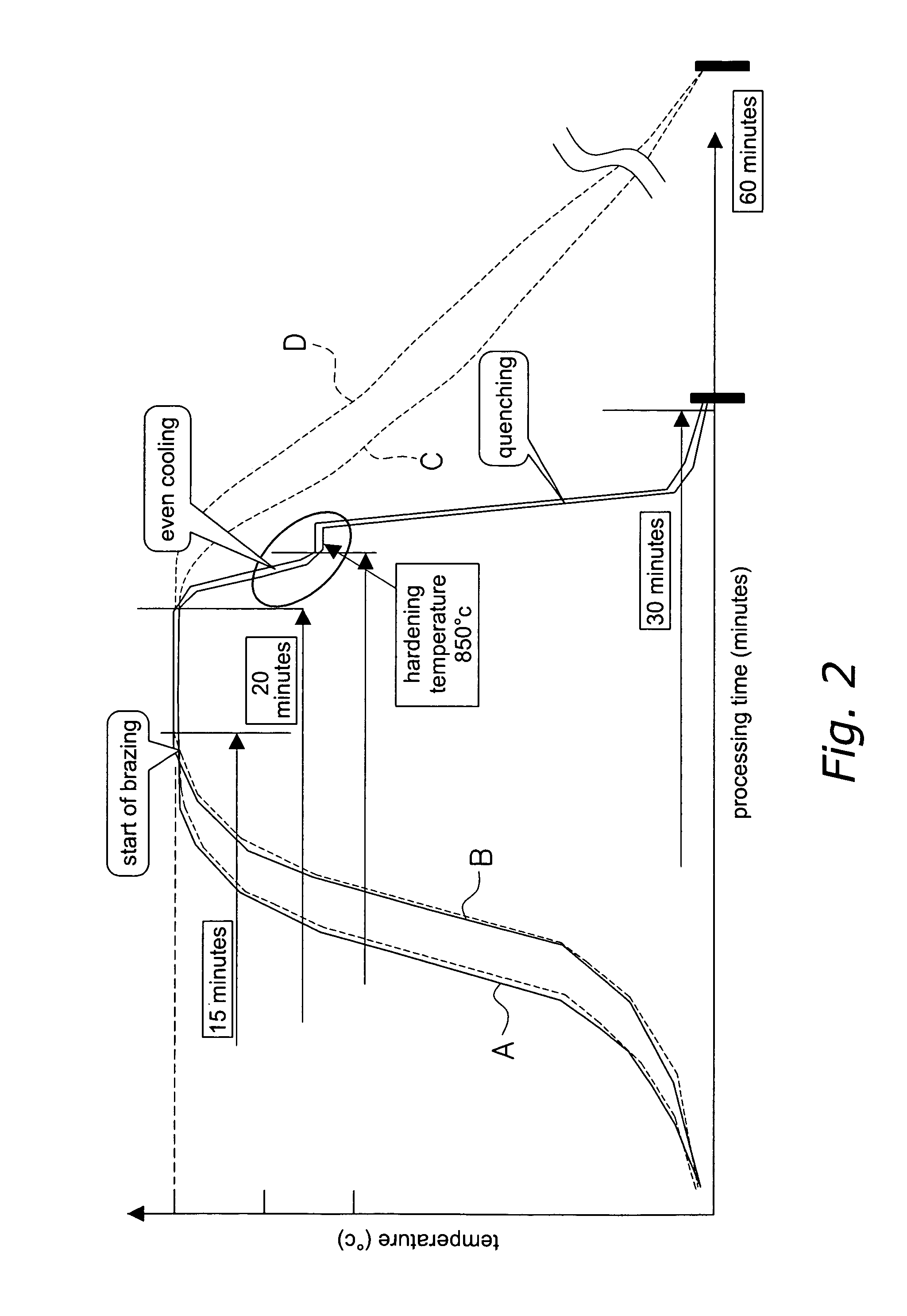
[0044] Here, according the following procedure, regarding the turbine shell and the turbine blades of the rotary member manufactured by the method for manufacturing according to the present invention, a degree of recovery of the properties is evaluated.

[0045] First, two test specimens (a tensile test specimen and an impact test specimen) were formed of material (SPHC), which were the same as those of the turbine shell and the turbine blades. The tensile test specimen was No. 5 tensile test specimen (thickness: 1.49 to 1.59 mm) formed according to JIS Z 2201. The impact test specimen was 2V test specimen (three-ply thickness: 4.75 to 4.87 mm) formed according to JIS Z 2202.

[0046] Next, three processes were performed on each of the test specimens: 1) no heat treatment was performed; 2) only brazing was performed; and 3) hardening was performed in addition to the brazing. In the hardening of 3), temperin...


PUM

PropertyMeasurementUnit
temperatureaaaaaaaaaa
melting pointaaaaaaaaaa

Abstract

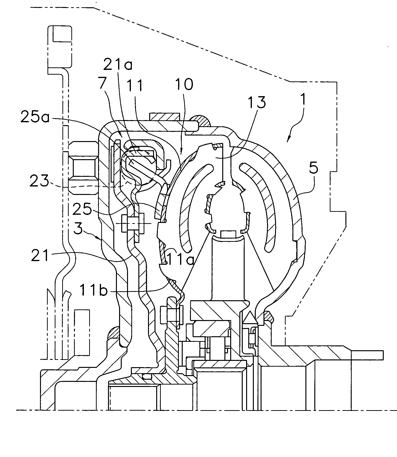
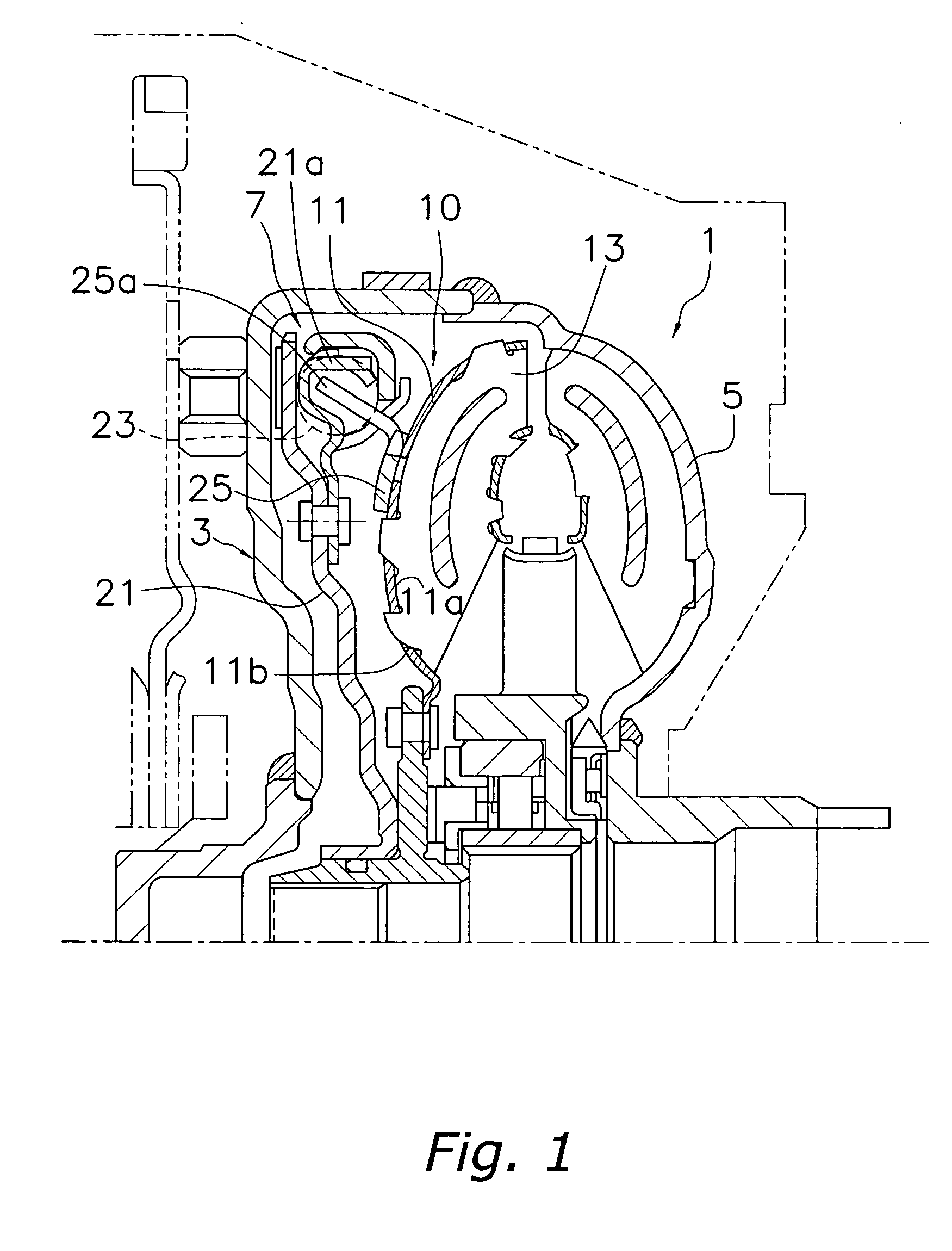
It is an object of the present invention to cut costs in manufacturing a rotary member of a torque converter. A method for manufacturing a rotary member of a torque converter 1 is a method for includes manufacturing a rotary member 10 constituted by a turbine shell 11 of the torque converter 1, a plurality of turbine blades 13 fixed to an inner face 11a of the turbine shell 11, and a driven plate 25 of a lock-up device 7 fixed to an outer face 11b of the turbine shell 11. The method includes a first step, a second step, and a third step. In the first step, the driven plate 25 is fixed to the turbine shell 11. In the second step, the turbine blades 13 are brazed to the turbine shell 13 by heating the turbine shell 11 and the turbine blades 13. In the third step, the rotary member 10 is quenched after the heat treatment in the second step.

Description

TECHNICAL FIELD [0001] The present invention relates to a method for manufacturing a rotary member of a torque converter, and particularly to a method for manufacturing a rotary member constituted by a turbine shell, a plurality of blades, and a driven plate. [0002] Furthermore, the present invention relates to a rotary member of a torque converter manufactured by the method. BACKGROUND ART [0003] A torque converter includes three kinds of vane wheels (an impeller, a turbine, and a stator) in a working oil chamber and transmits torque from an input rotary member to an output rotary member through a working oil. The turbine is connected to an output member and includes a turbine shell and a plurality of turbine blades. The turbine shell is an annular member bulging toward the front cover on the engine side. The turbine blades are disposed radially and fixed to an inner face of the turbine shell. [0004] Torque converters having a lock-up device to prevent the loss of energy due to flu...

Claims


Application Information

Patent Timeline
Patent Type & Authority Applications(United States)
IPC IPC(8): B23P15/04F16H41/28F16H45/02F16H61/14
CPCF16H45/02Y10T29/4932F16H61/14F16H41/28
Inventor MURATA, IKUO
Owner EXEDY CORP
Learn More