Eureka AIR delivers breakthrough ideas for toughest innovation challenges, trusted by R&D personnel around the world.

Dynamic bandwidth allocation apparatus and method

a bandwidth allocation and dynamic technology, applied in the field of adaptive allocation apparatus for radio channels, can solve the problems of complex bandwidth allocation determination scheme, difficult to apply to a substantial communication system, and difficult to determine the effective bandwidth of video traffic in advance, so as to reduce the current bandwidth by a large amoun

Inactive Publication Date: 2007-06-14
KT CORP +2
View PDF5 Cites 140 Cited by
  • Summary
  • Abstract
  • Description
  • Claims
  • Application Information

AI Technical Summary

Benefits of technology

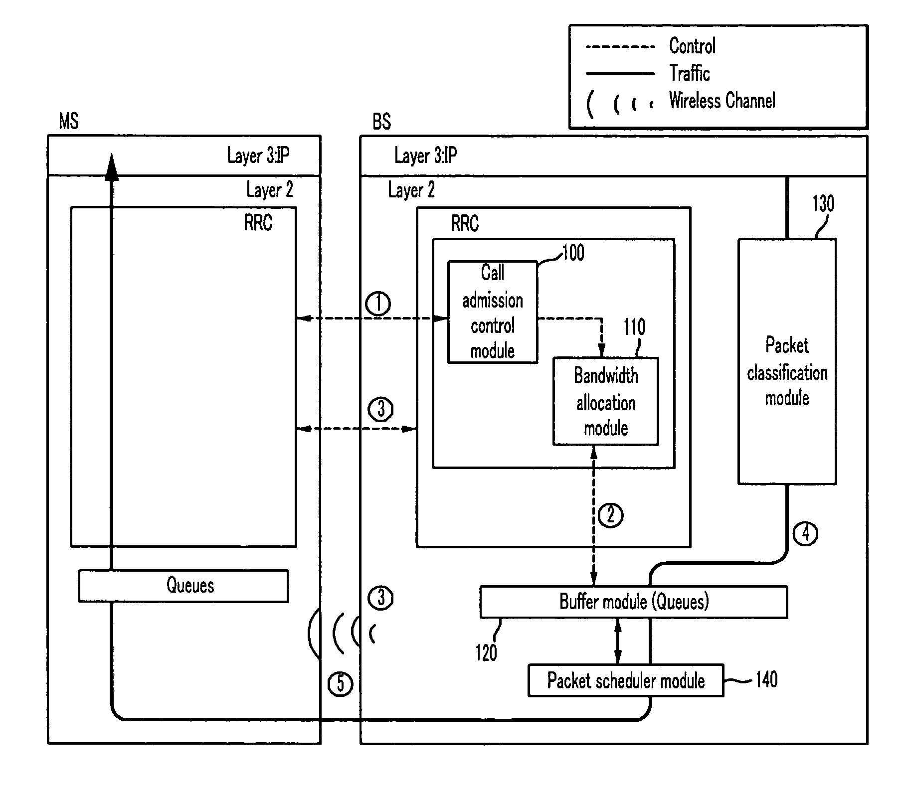
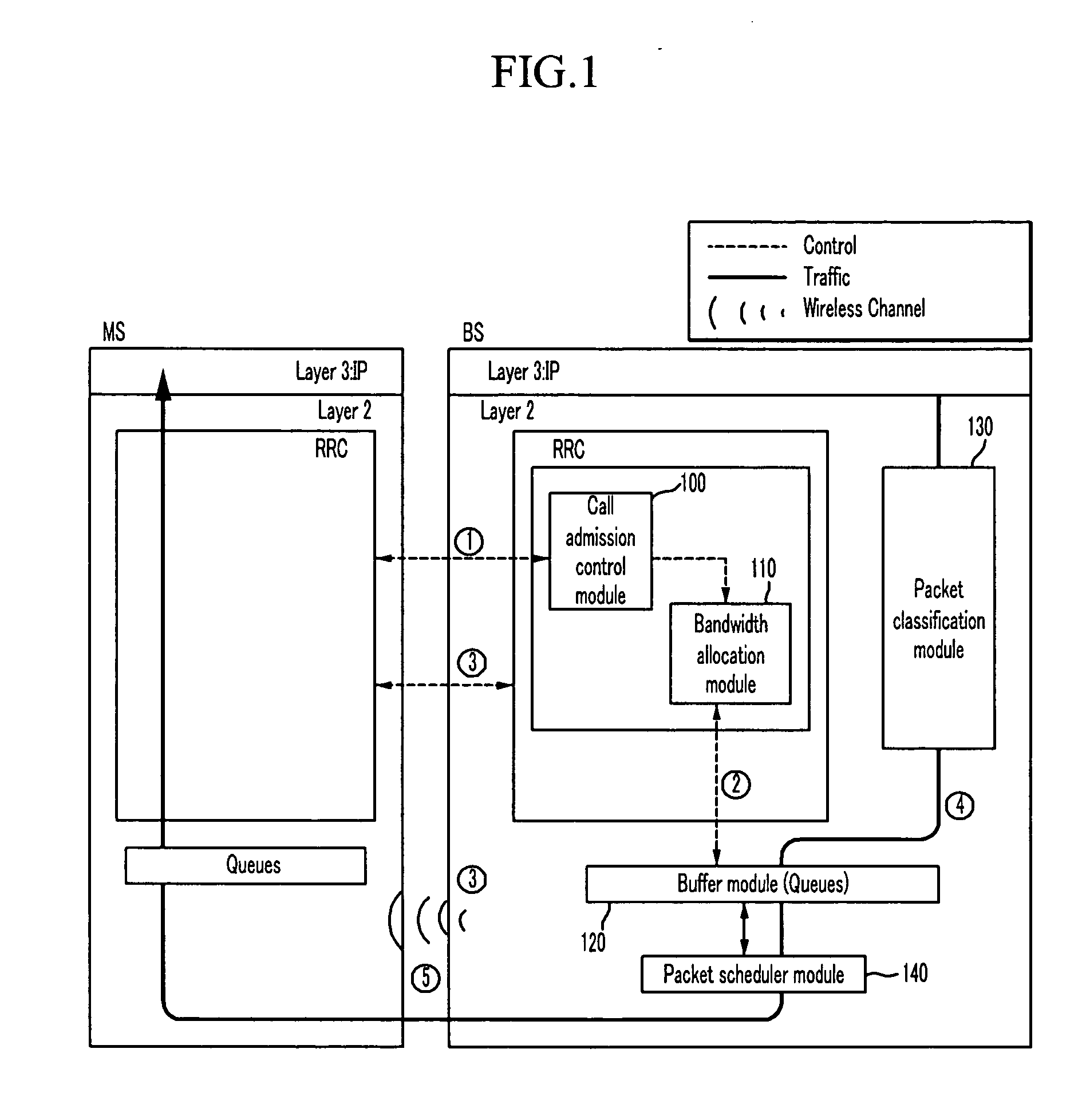
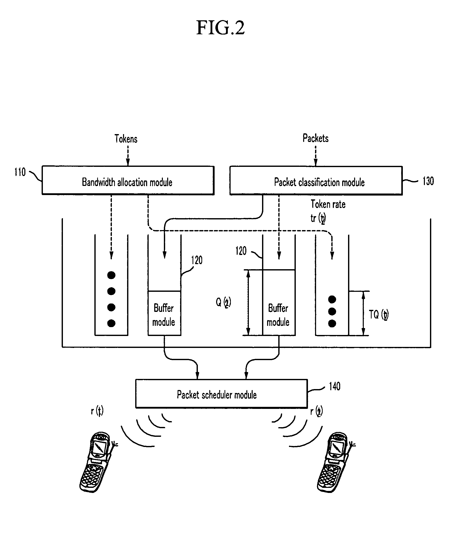
The present invention provides a bandwidth allocation apparatus and method for adaptively allocating bandwidths in a mobile communication system. The apparatus includes a call admission control module, a packet classification module, a buffer module, a packet scheduler module, and a bandwidth allocation module. The method includes the steps of allocating bandwidth to process traffic services, comparing the current queue length and minimum queue length, determining which one is greater, and reducing the current bandwidth if the packet loss rate is low. The technical effect of the invention is to improve the efficiency of bandwidth allocation and reduce network congestion.

Problems solved by technology

The bandwidth allocation determination scheme will be more complex in the future since various types of traffic will be generated as user traffic is changed from small-capacity voice and data communication to large-capacity multimedia communication.
The concept of the effective bandwidth scheme is quite attractive, but it is difficult to apply to a substantial communication system.
Also, it is difficult to determine an effective bandwidth for video traffic in advance.
However, multimedia traffic services having various features have distinctive service characteristics, and accordingly they cannot be indiscriminately controlled by the conventional communication QoS scheme.

Method used


Image

  • Dynamic bandwidth allocation apparatus and method
  • Dynamic bandwidth allocation apparatus and method
  • Dynamic bandwidth allocation apparatus and method

Examples


Embodiment Construction

[0021] An exemplary embodiment of the present invention will hereinafter be described in detail with reference to the accompanying drawings.

[0022] In the following detailed description, only certain exemplary embodiments of the present invention have been shown and described, simply by way of illustration. As those skilled in the art would realize, the described embodiments may be modified in various different ways, all without departing from the spirit or scope of the present invention. The drawings and description are to be regarded as illustrative in nature and not restrictive, and like reference numerals designate like elements throughout the specification.

[0023] Throughout this specification and the claims which follow, unless explicitly described to the contrary, the word “comprise” or variations such as“comprises” or “comprising” will be understood to imply the inclusion of stated elements but not the exclusion of any other elements.

[0024] In addition, throughout this spec...


PUM


Abstract

The present invention relates to a bandwidth allocation apparatus and a method thereof. The present invention provides a method for adaptively allocating and controlling radio channels to multimedia traffic having various characteristics. Particularly, the present invention proposes a method for maximizing a system resource use rate while satisfying a communication QoS requirement for individual video traffic. Therefore, the adaptive bandwidth allocation method according to the present invention guarantees system performance and user-required communication QoS.

Description

CROSS-REFERENCE TO RELATED APPLICATION [0001] This application claims priority to and the benefit of Korean Patent Application Nos. 10-2005-0119982 and 10-2006-0041347 respectively filed in the Korean Intellectual Property Office on Dec. 8, 2005 and May 9, 2006, the entire contents of which are incorporated herein by reference. BACKGROUND OF THE INVENTION [0002] (a) Field of the Invention [0003] The present invention relates to a bandwidth allocation apparatus and a method thereof. More particularly, the present invention relates to an apparatus for adaptively allocating radio channels in a mobile communication system, and a method thereof. [0004] (b) Description of the Related Art [0005] The next generation mobile communication system will mainly handle multimedia traffic services having various features. [0006] Thus, the next generation mobile communication system controls a bandwidth for efficient processing of multimedia traffic while satisfying communication quality of service ...

Claims


Application Information

Patent Timeline
Patent Type & Authority Applications(United States)
IPC IPC(8): H04L12/26H04Q7/00H04J3/22H04L12/54H04W72/04
CPCH04L12/5693H04L29/06027H04L47/10H04L65/80H04L47/215H04L47/2441H04L47/527H04L47/14H04L47/50H04W28/02H04L65/1101H04W8/04
Inventor CHOI, SUNG-GUPARK, JI-SOOPARK, SOON-GISONG, JAE-SUNAM, SANG-WOOSHIN, YEON-SEUNGKIM, YEONG-JIN
Owner KT CORP
Why Eureka
Eureka Blog
Learn More