Eureka AIR delivers breakthrough ideas for toughest innovation challenges, trusted by R&D personnel around the world.

Dynamic bandwidth allocation device and method of passive optical network

A technology of dynamic bandwidth allocation and passive optical network, which is applied in the field of optical communication, can solve the problems of irregular data transmission, singleness, and incapable of bandwidth allocation and processing, so as to effectively utilize bandwidth resources, improve bandwidth utilization, and avoid resource waste Effect

Active Publication Date: 2007-12-12
HUAWEI TECH CO LTD
View PDF1 Cites 58 Cited by
  • Summary
  • Abstract
  • Description
  • Claims
  • Application Information

AI Technical Summary

Problems solved by technology

[0018] In actual application, the above scheme has the following problems: it can only be applied to a system of a single nature, it cannot distinguish and process different types of business according to different strategies, and it cannot satisfy various The QoS requirements of the service type cannot allocate bandwidth according to the user service port, and cannot dynamically handle the situation that the ONU is offline
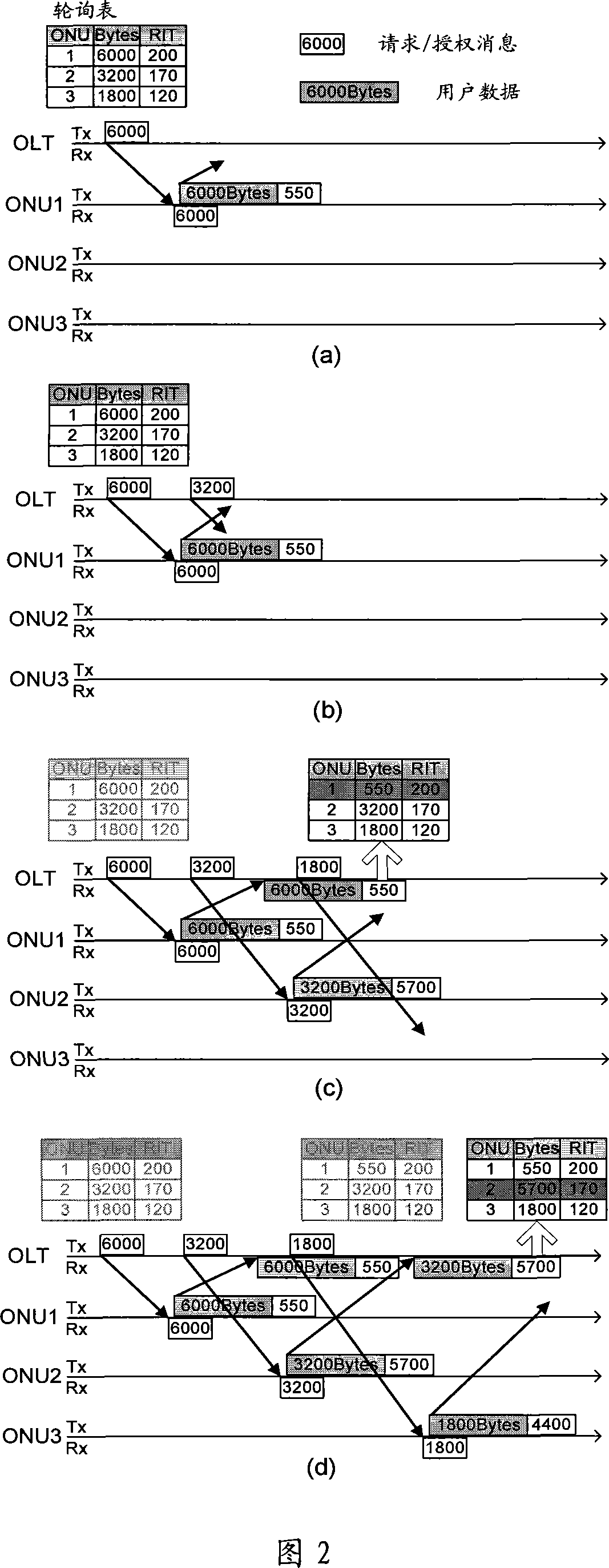
[0019] One of the main reasons for this situation is that there are no different allocation strategies for different services; the polling period in technical solution 1 is adaptively changed with the amount of data, resulting in irregular data transmission for the same service, which cannot meet the time limit. Extend the demand of uniform real-time business; Adopt the Round-Robin type fixed sequence round-robin in the technical scheme two, be specially aimed at connection-oriented, the APON application of the fixed length of the protocol data unit (Protocol Data Unit, referred to as "PDU"), and The bandwidth update mechanism is aimed at T-CONT, and bandwidth allocation cannot be performed according to different ports.

Method used


Image

  • Dynamic bandwidth allocation device and method of passive optical network
  • Dynamic bandwidth allocation device and method of passive optical network
  • Dynamic bandwidth allocation device and method of passive optical network

Examples


Embodiment Construction

[0070] In order to make the object, technical solution and advantages of the present invention clearer, the present invention will be further described in detail below in conjunction with the accompanying drawings.

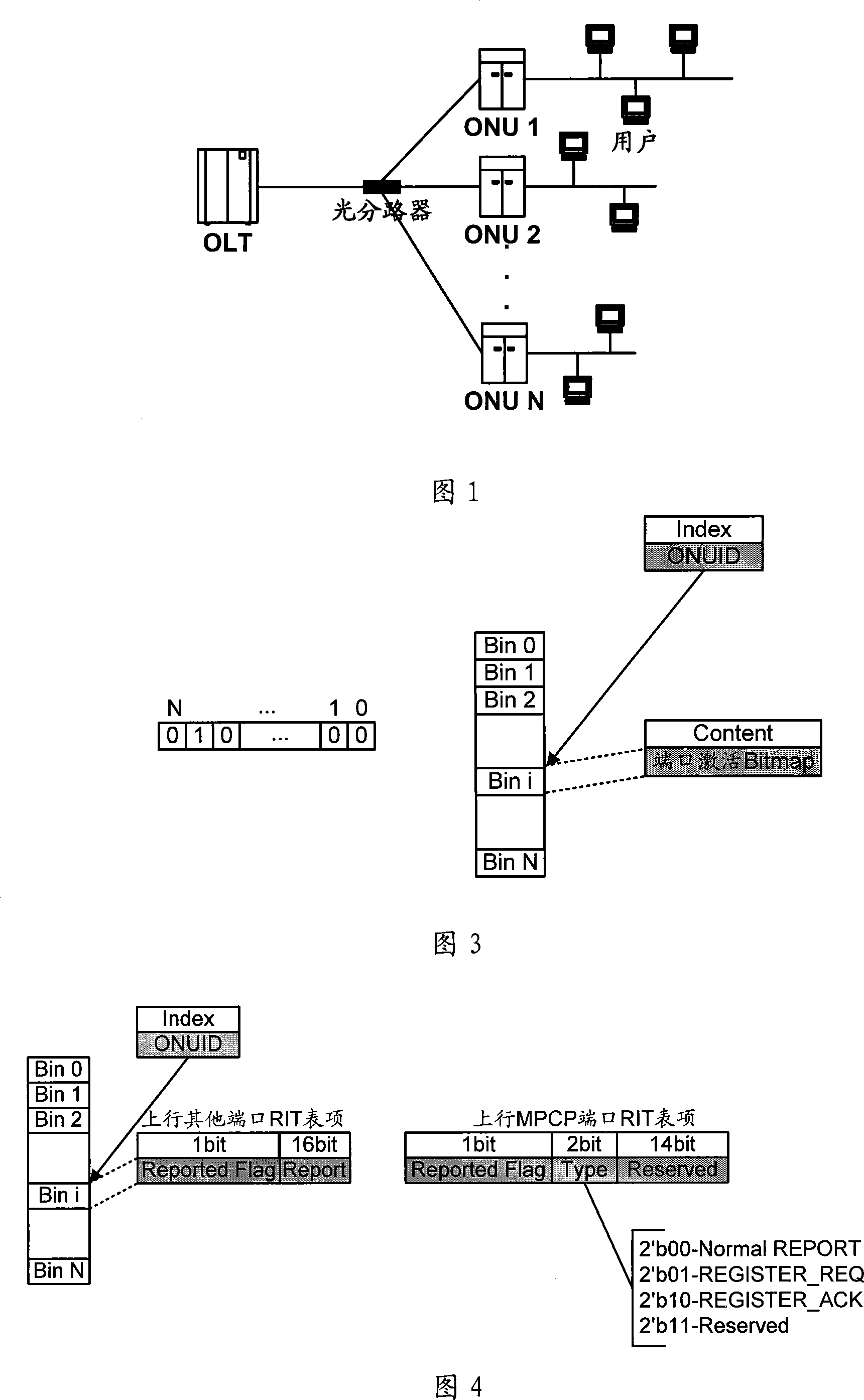
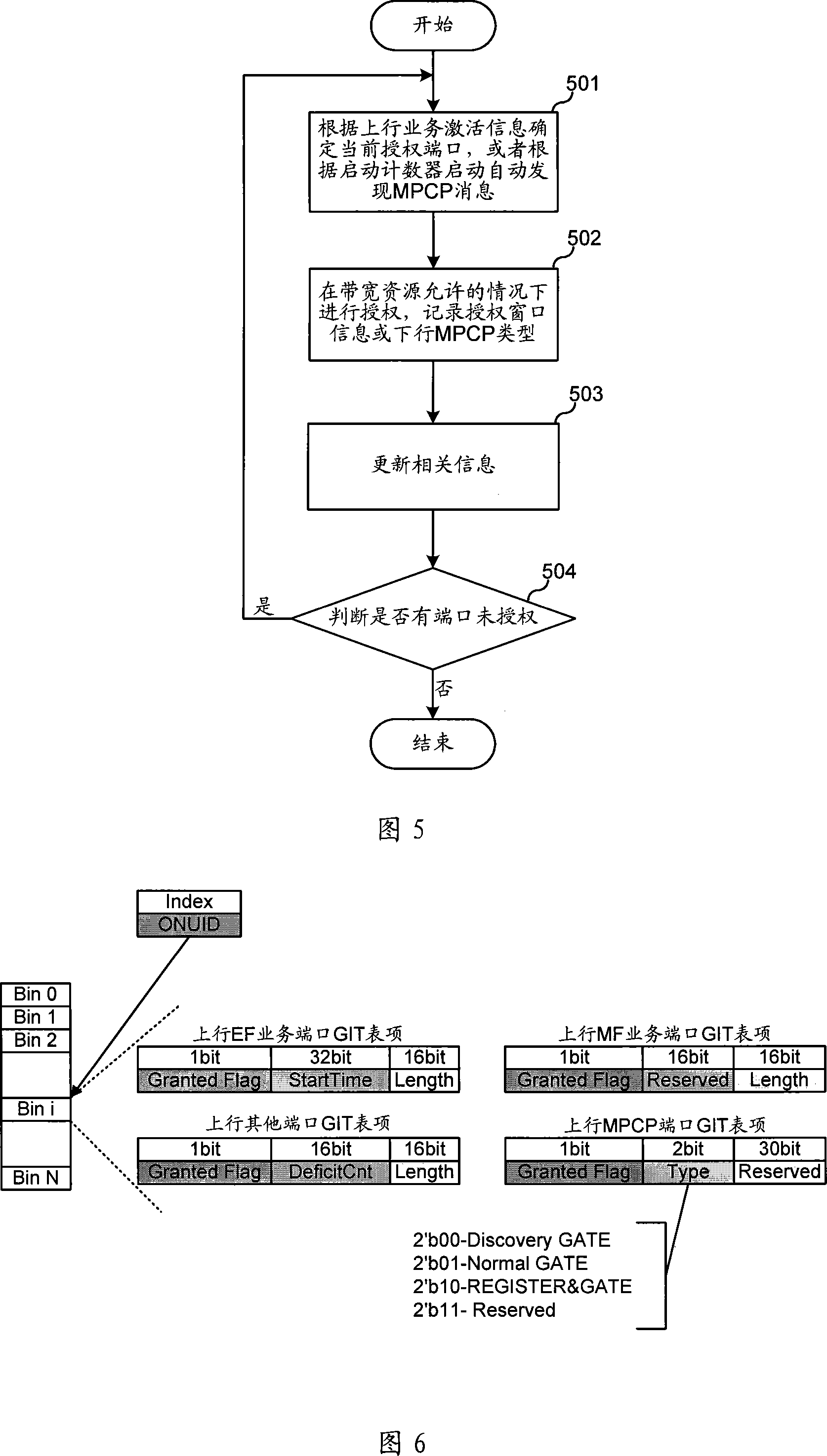
[0071] First of all, it needs to be pointed out that the dynamic bandwidth allocation method for passive optical network proposed by the present invention includes service registration, bandwidth allocation, authorization message, and ONU information aging. The invention classifies various services, and arranges different data structures for different types of services to implement different allocation strategies. The present invention also handles different ports under the same ONU separately. In addition, the present invention also monitors the state of the ONU, and dynamically releases the resource of the offline ONU. An embodiment of the present invention is described in detail below.

[0072] In order to classify services and process different ports separat...


PUM


Abstract

The invention relates to optical communication field, discloses a collating device and method for dynamic bandwidth in source-free optical network, and the distribution method for dynamic bandwidth is transparent, which can satisfy the requirement for different service, improve the utilization rate of bandwidth, realize the fair distribution for bandwidth, good haleness, real time, and can distribute bandwidth for different port, and support to release offline bandwidth of ONU. The distributing device for dynamic bandwidth in source-free optical network includes ascending service active fiber network unit bit-mapping register, ascending service active port bit-mapping table, ascending virtual media accessing control sub-layer information table, descending virtual media accessing control sub-layer authorization information table; said distributing device for dynamic bandwidth, consults said fiber network unit active information, port active information and length information of sending data, according to preset priority of different service, process the service flow according to priority according to preset priority, and distributes the dynamic bandwidth for ports.

Description

technical field [0001] The invention relates to the field of optical communication, in particular to a dynamic bandwidth allocation device and method for a passive optical network. Background technique [0002] Passive Optical Network ("PON" for short) means that the optical distribution network does not contain any electronic devices and electronic power supplies, and is all composed of passive devices such as optical splitters, and does not require expensive active electronic equipment. An optical access network. As an emerging broadband access optical fiber technology covering the last mile, PON does not require node equipment at the optical branch point, and only needs to install a simple optical splitter, so it has the advantages of saving optical cable resources, sharing bandwidth resources, saving It has the advantages of investment in computer room, high equipment security, fast network construction speed, and low comprehensive network construction cost. The low co...

Claims


Application Information

Patent Timeline
IPC IPC(8): H04L12/54H04L12/24H04B10/12H04Q11/00
Inventor 谭培龙赵峻刘昱洪建明
Owner HUAWEI TECH CO LTD
Why Eureka
Eureka Blog
Learn More