
Headspace sealing and displacement method for removal of vacuum pressure

a vacuum pressure and headspace sealing technology, applied in the direction of containers, liquid dispensing, packaging under special atmospheric conditions, etc., can solve the problems of vacuum pressure, reduced liquid volume in containers, and vacuum pressur

Inactive Publication Date: 2007-06-14
MELROSE DAVID MURRAY
View PDF10 Cites 45 Cited by
  • Summary
  • Abstract
  • Description
  • Claims
  • Application Information

AI Technical Summary

Benefits of technology

[0023] In view of the above, it is an object of one possible embodiment of the present invention to provide a headspace sealing and displacement method that can provide for removal of vacuum pressure such that there is substantially no remaining force within the container.

Problems solved by technology

Once the liquid cools down in a capped container, however, the volume of the liquid in the container reduces, creating a vacuum within the container.
This liquid shrinkage results in vacuum pressures that pull inwardly on the side and end walls of the container.
This in turn leads to deformation in the walls of plastic bottles if they are not constructed rigidly enough to resist such force.
Even with such substantial displacement of vacuum panels, however, the container requires further strengthening to prevent distortion under the vacuum force.
The liquid shrinkage derived from liquid cooling, causes a build up of vacuum pressure.
The more difficult the structure is to deflect inwardly, the more vacuum force will be generated.
In prior art proposals, a substantial amount of vacuum may still be present in the container and this tends to distort the overall shape unless a large, annular strengthening ring is provided in horizontal, or transverse, orientation typically at least a ⅓ of the distance from an end to the container.
A problem exists when locating such transversely oriented panels in the container side-wall, or end-wall or base region, even after vacuum is removed completely from the container when the liquid cools down and the panel is inverted.
This refrigeration provides further product contraction and in containers with very little sidewall structure, so-called ‘glass look-a-like’ bottles, there may therefore be some panelling that occurs on the containers that is unsightly.
This situation is very hard to engineer successfully, however, as it depends on utilising a larger headspace in order to compress at base inversion time, and it is less desirable to introduce a larger headspace to the container than is necessary in order to retain product quality.
While it is desirable to have the liquid level in the container drop, to avoid spill when opened by the consumer, it has been found that providing too much positive pressure potential within the base may cause some product spill when the container is opened, particularly if at ambient temperatures.
Headspace contains gases that in time can damage some products or place extra demands on container structural integrity.
Filling and sealing a rigid container at elevated temperatures can create significant vacuum forces when excessive headspace gas is also present.
However, even with containers such as described in the abovementioned PCT specifications where there is little residual vacuum pressure, the neck finish of the container is still required to be very thick in order to withstand the temperature of fill.

Method used


Image

  • Headspace sealing and displacement method for removal of vacuum pressure
  • Headspace sealing and displacement method for removal of vacuum pressure
  • Headspace sealing and displacement method for removal of vacuum pressure

Examples


Embodiment Construction

[0057] The following description of preferred embodiments is merely exemplary in nature, and is in no way intended to limit the invention or its application or uses.

[0058] As discussed above, to accommodate vacuum forces during cooling of the contents within a heat set container, containers have typically been provided with a series of vacuum panels around their sidewalls and an optimized base portion. The vacuum panels deform inwardly, and the base deforms upwardly, under the influence of the vacuum forces. This prevents unwanted distortion elsewhere in the container. However, the container is still subjected to internal vacuum force. The panels and base merely provide a suitably resistant structure against that force. The more resistant the structure the more vacuum force will be present. Additionally, end users can feel the vacuum panels when holding the containers.

[0059] Typically at a bottling plant the containers will be filled with a hot liquid and then capped before being ...


PUM


Abstract

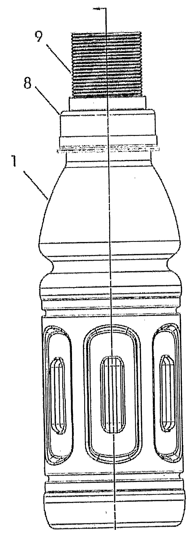
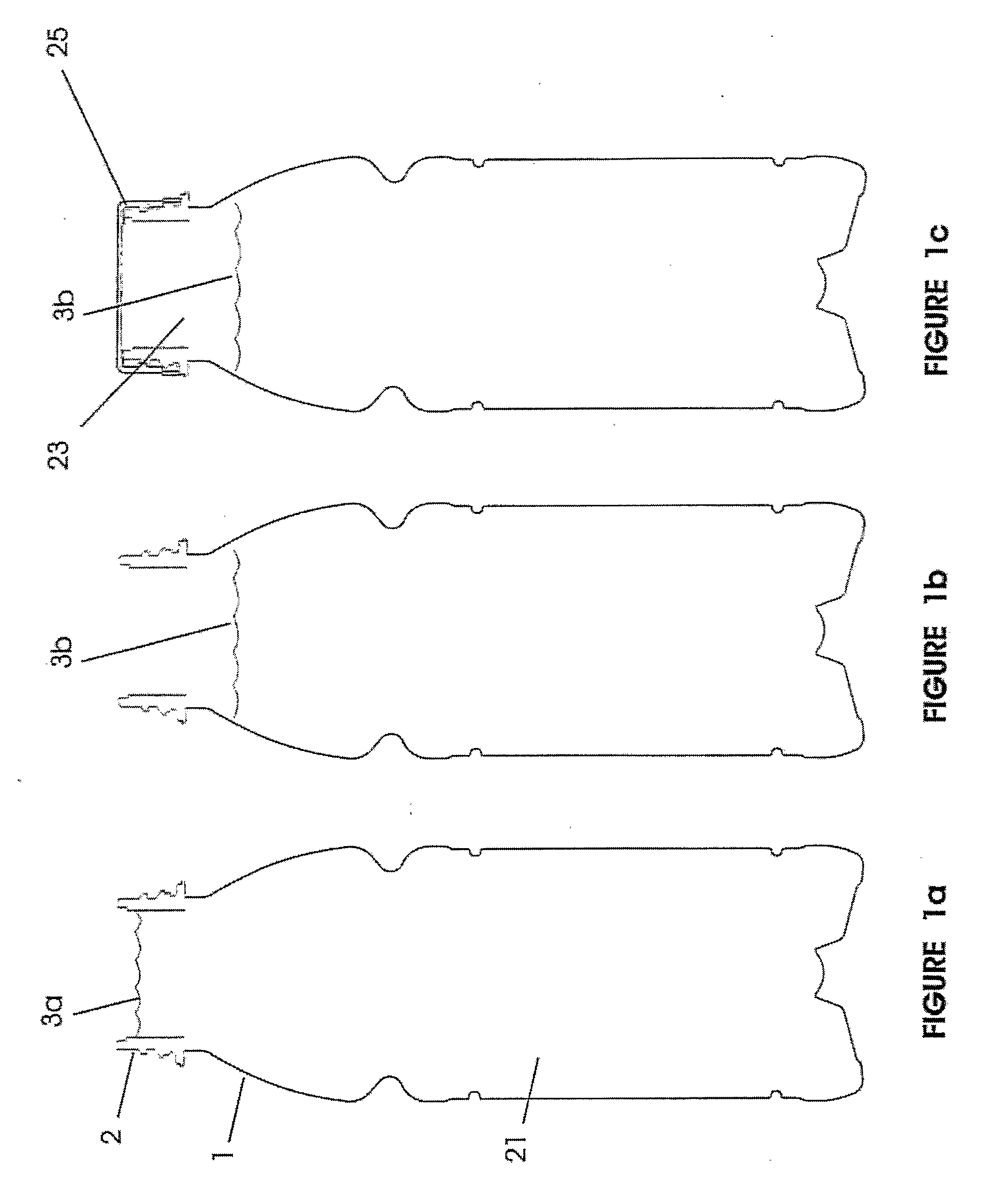
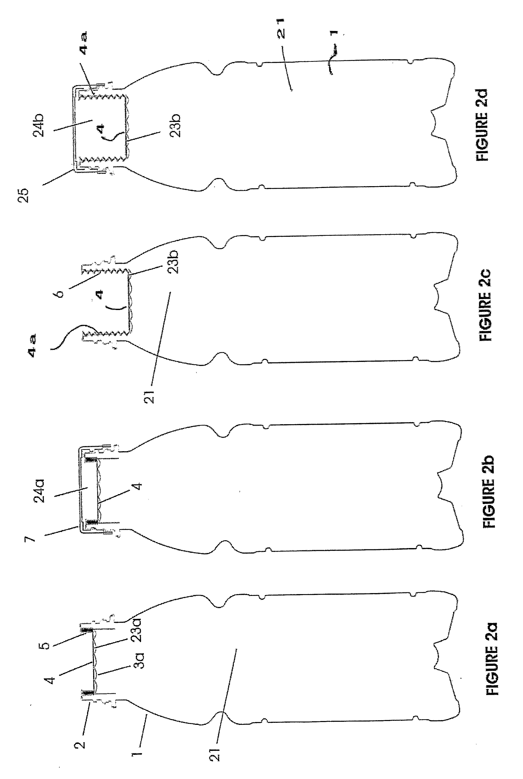
A container (1) is intended for filling with a hot liquid (21). The container (1) has a neck finish (2) with an opening closed off by a primary seal (4) which has an expandable side wall (4a). As the liquid (21) cools, the side wall (4a) is drawn into the container (1) to remove vacuum pressure created within the container (1). A permanent cap (25) can provide a secondary seal for the container and define a secondary headspace (24b) between the primary and secondary seals (4) (25). In other embodiments the seal (4) can be replaced by a mechanically movable seal which may be locked in its downward position. Also the secondary seal can be provided with a port or aperture to provide access into the secondary headspace for a commodity. Also a commodity such as a tablet or pill may be provided within the secondary headspace

Description

TECHNICAL FIELD OF THE INVENTION [0001] This invention relates generally to a method of light-weighting hot fill containers by utilising a container sealing structure that provides for the removal of vacuum pressure. This is achieved by filling a container with a heated fluid, liquid will now be referred to, sealing the neck finish of the container with a moveable sealing structure during the hot fill process. The sealing structure is then displaced inwardly to negate vacuum forces generated within the container following liquid cooling. The sealing structure thereby displaces the liquid below the headspace in the upper neck region of the container downwardly prior to finally capping and labelling the container. This invention further relates to hot-filled and pasteurized products packaged in heat-set polyester containers and is particularly useful for packaging oxygen sensitive foods and beverages where a longer shelf life is desirable. BACKGROUND [0002] So called ‘hot fill’ contai...

Claims


Application Information

Patent Timeline
Patent Type & Authority Applications(United States)
IPC IPC(8): B65D90/02B65D1/04B65D39/00A47J39/00B65B31/02B65D1/02B65D39/12B65D41/04B65D41/62B65D51/18B65D81/32B65D85/72
CPCB65B31/00B67C3/045B65D79/005B65B61/24B67C2003/226B65D79/0087B65B31/02B65D39/12B65D41/04B65D51/18
Inventor MELROSE, DAVID MURRAY
Owner MELROSE DAVID MURRAY
Learn More