
A VOIP communication system

a communication system and communication system technology, applied in the field of voip communication system, can solve the problems of slow communication, more expensive, slow process, etc., and achieve the effect of fast and effective execution

Inactive Publication Date: 2007-06-07
OBIE TECH LLC
View PDF23 Cites 9 Cited by
  • Summary
  • Abstract
  • Description
  • Claims
  • Application Information

AI Technical Summary

Benefits of technology

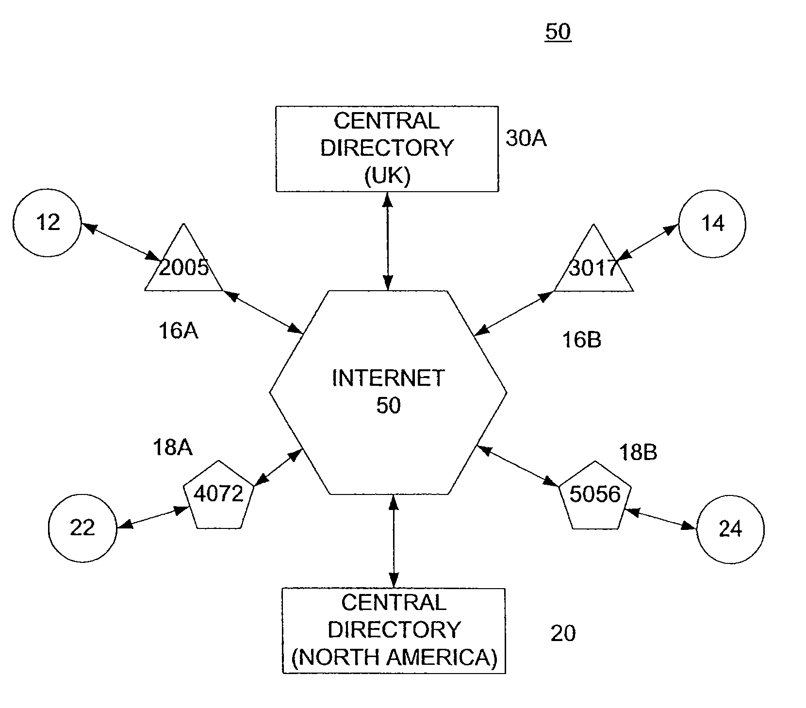
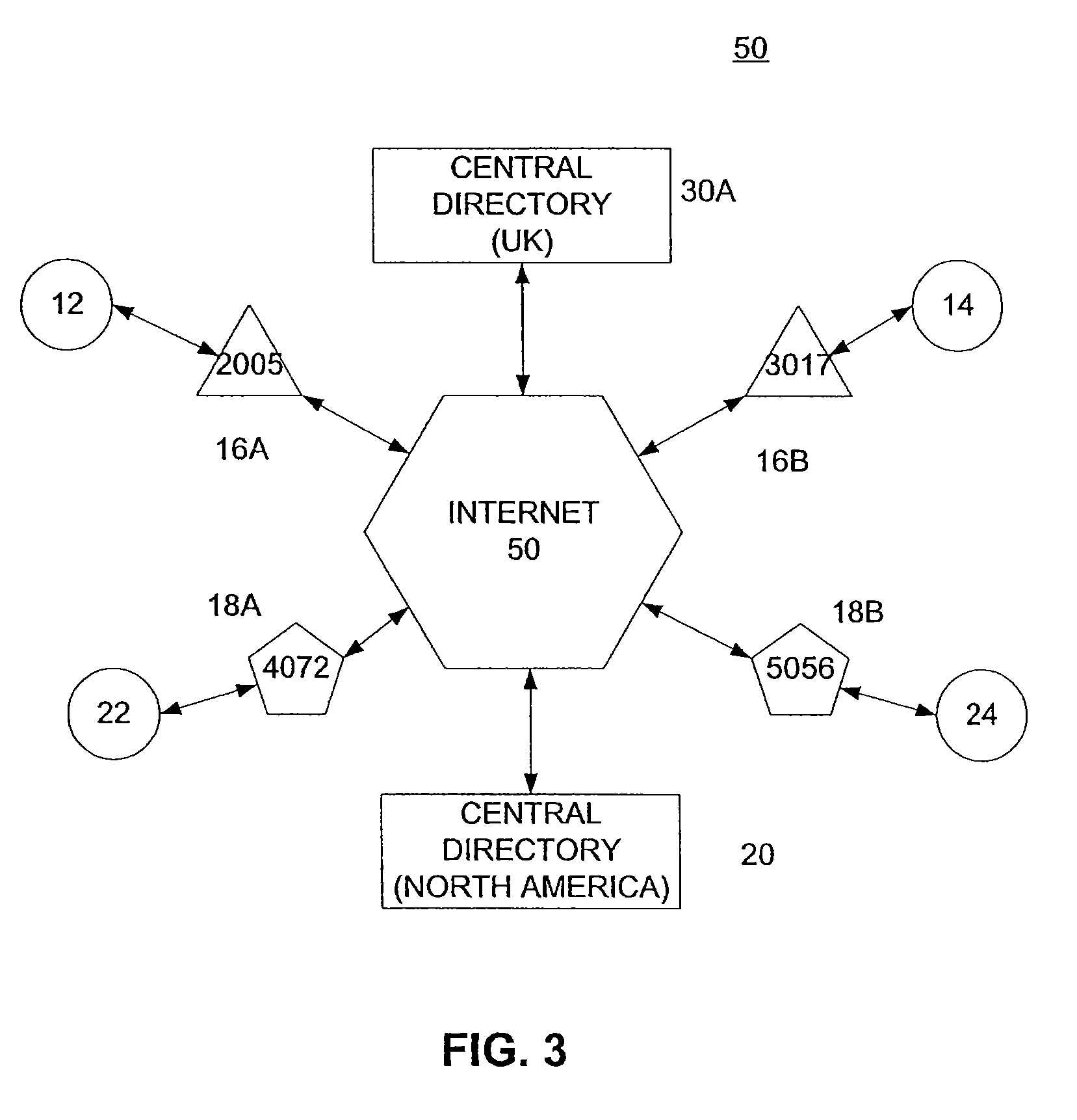
[0013] Importantly, within the central directory, each listed telephone number is used as a record with an entry associated with each data number. This data at each entry identifies, directly or indirectly, the respective ISP gateway by an Internet designation such as its IP address or SIP URL. This configuration insures that a request by any subscriber for a connection (VOIP, VIP, etc. . . . ) to another subscriber of any ISP is executed quickly and effectively.

Problems solved by technology

A major stumbling block for the spread of VOIP communications is that each user has a telephone line assigned by a telephone company and an Internet connection (such as a Domain Name or IP address) that is separate and unrelated to the user's telephone line.
Understandably, this approach is much slower than the pure Internet lines, and more expensive.
Of course, depending on the distance between the respective nodes, this may be a very slow process.
A further problem faced by ISPs is that each has its own type of equipment and internal protocols; hence, even if a line is established between two subscribers of different ISPs, communication may not take place because of system incompatibilities.
However, the problem with all these schemes is that if the data banks contain entries for all the subscribers, the amount of time required to find the proper IP address from a telephone number becomes prohibitive and unacceptable to subscribers who are used to the almost instantaneous response of most POTS switching systems.

Method used


Image

  • A VOIP communication system
  • A VOIP communication system
  • A VOIP communication system

Examples


Embodiment Construction

[0019]FIG. 1 is a somewhat simplified block diagram of a prior art VOIP system that provides communication only between the subscribers of the same ISP. More specifically, in system 10, two devices 12, 14 are subscribers of an ISP 16 while two other devices 22, 24 are subscribers of an ISP 26. Gateways 16A, 16B are controlled by ISP 16 and connect devices 12, 14, respectively, to the Internet 50. Similarly, gateways 26A, 26B are controlled by ISP 26 and connect devices 22, 24, respectively, to the Internet 50. The two ISPs 16, 26 have no knowledge of each other's gateway, and do not have any means of handling requests for services that are not within their networks. Therefore, in this configuration, the users of devices 12, 14 can request direct VOIP / VIP communications only between each other or with other subscribers of ISP 16 but not with subscribers 22, 24 of ISP 26. Other voice communication can be established only through external PBXs and / or POTS (these have been omitted from ...


PUM


Abstract

An Internet-based system provides substantially instantaneous communication between two devices for exchanging voice and multimedia signals. The system includes ISP gateways with unique IDs that service a plurality of devices with unique telephone numbers. The system further includes a directory which correlates the devices with ISP gateways. More specifically, the directory includes a RELATIVE records / words / cells in a RANDOM ACCESS TABLE (RRAT) with each entry being identified by a record number, which in this case corresponds to the telephone numbers (as they are or in reverse). The entry relates directly or indirectly the telephone number with the respective ISP gateway. Communication is established by having the ISP gateway of the calling device looking up the ISP gateway of the called device in the directory using the telephone number of the called device. The ISP gateway then generates a handle for the called ISP and uses the handle to establish a communication channel between two devices quickly and efficiently.

Description

RELATED APPLICATIONS [0001] The subject application is a continuation-in-part of commonly assigned application Ser. No. 11 / 295,977 filed Dec. 7, 2005 and incorporated herein by reference, now ______.BACKGROUND OF THE INVENTION [0002] A. Field of Invention [0003] This invention pertains to systems providing IP communications over the Internet including VOIP (Voice Over IP) and VIP (Video over IP). More specifically, a system and method is described that provides efficient IP (VOIP, VIP etc. . . . ) communications between various different internet service providers (ISPs). [0004] B. Description of the Prior Art [0005] Providing telephone (and video) communications wholly or partially over the Internet has been found to be advantageous, More and more entities (including large and small businesses, non-profit organizations, state and federal agencies and individuals) have Internet connections, and most of these connections are broadband connections that provide much more bandwidth than...

Claims


Application Information

Patent Timeline
IPC IPC(8): H04L12/56
CPCH04L29/06027H04L29/12132H04L29/1216H04L61/1552H04L61/157H04L65/1069H04L69/08H04M7/1285H04L65/1043H04L65/104H04L65/103H04L61/4535H04L61/4552H04L61/4557H04L65/1101
Inventor ALUF-MEDINA, MARIO
Owner OBIE TECH LLC
Learn More