
Portable electronic device and capacitive charger providing data transfer and associated methods

a capacitive charger and electronic device technology, applied in the field of portable electronic devices and battery chargers therefor, can solve the problems of increasing power consumption, inconvenience in user's recharging of batteries of portable electronic devices, and increasing power consumption of modern portable electronic devices

Active Publication Date: 2007-06-07
MALIKIE INNOVATIONS LTD
View PDF22 Cites 74 Cited by
  • Summary
  • Abstract
  • Description
  • Claims
  • Application Information

AI Technical Summary

Problems solved by technology

However, recharging the batteries for a portable electronic device may be an inconvenience to the user.
Compounding these inconveniences for the user is the potential increased power consumption by modern portable electronic devices.
Most portable electronic devices provide more functionality than their predecessors, which usually results in increased power consumption.
This means more frequent recharging of the batteries of the portable electronic device, which may result in more recharging inconvenience for the user.
Unfortunately for some of the above devices, a user may still need to monitor the charge level of the battery in the portable electronic device.
In addition, some of the above devices may require the user to precisely align the electrodes of the charging device with the electrodes in the device being charged.
Undesired electromagnetic interference (EMI) may also be generated by capacitive charging arrangements.
Also, many portable electronic devices may need to be synchronized with a personal computer (PC) and existing wireless links may not be secure and consume too much power.

Method used


Image

  • Portable electronic device and capacitive charger providing data transfer and associated methods
  • Portable electronic device and capacitive charger providing data transfer and associated methods
  • Portable electronic device and capacitive charger providing data transfer and associated methods

Examples


Embodiment Construction

[0014] The present description is made with reference to the accompanying drawings, in which preferred embodiments are shown. However, many different embodiments may be used, and thus the description should not be construed as limited to the embodiments set forth herein. Rather, these embodiments are provided so that this disclosure will be thorough and complete. Like numbers refer to like elements throughout, and prime and multiple prime notation are used to indicate similar elements in alternate embodiments.

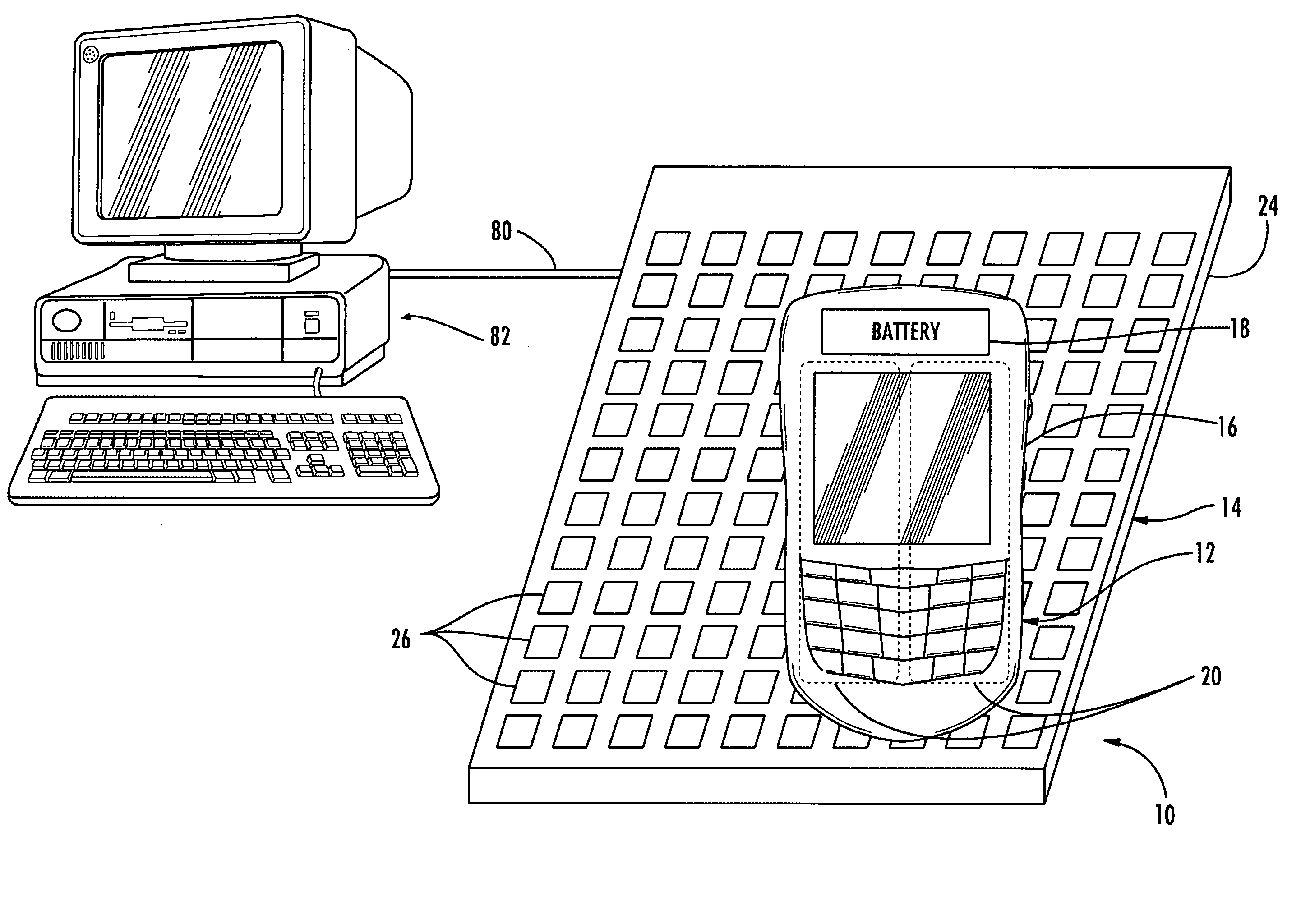
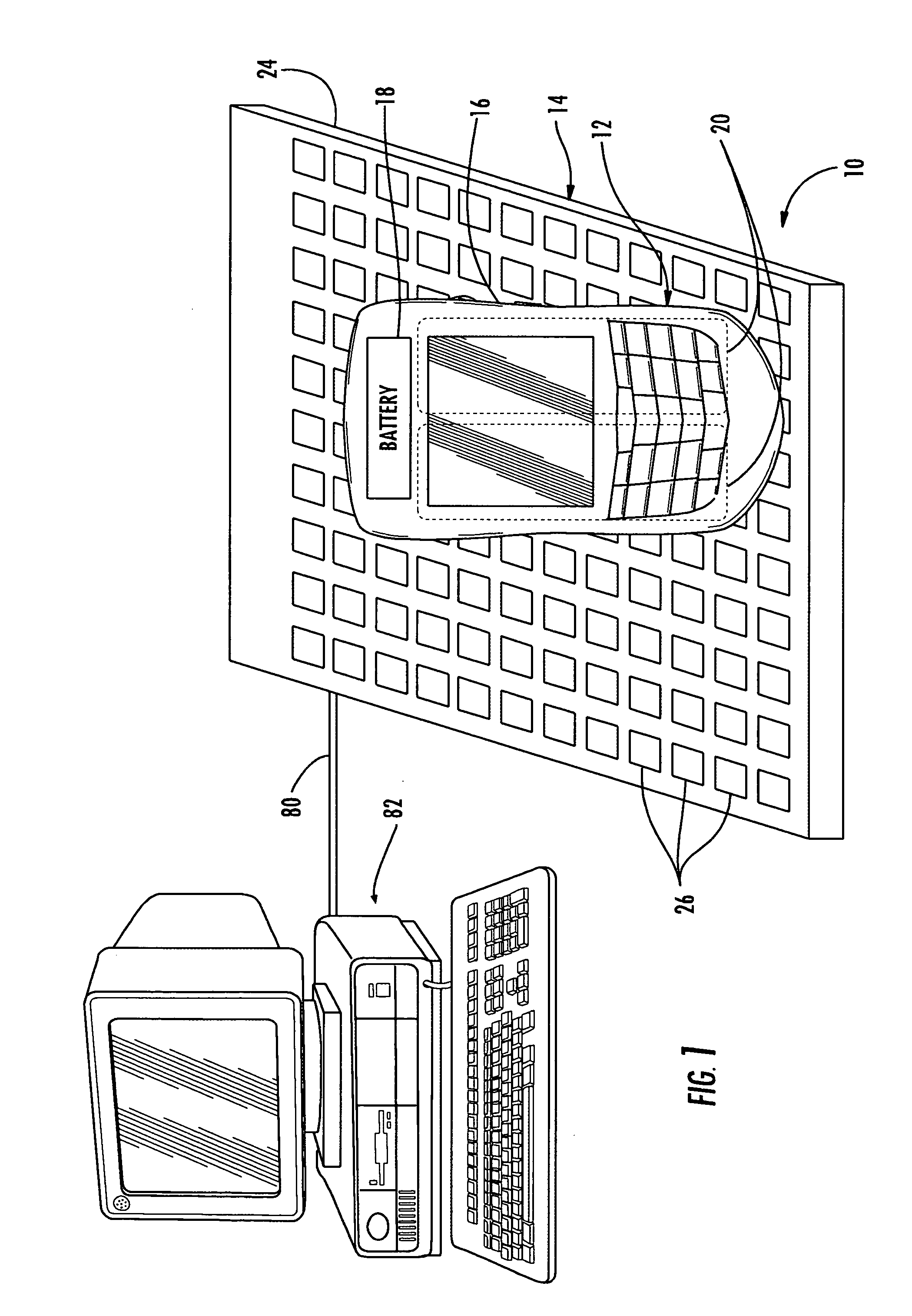
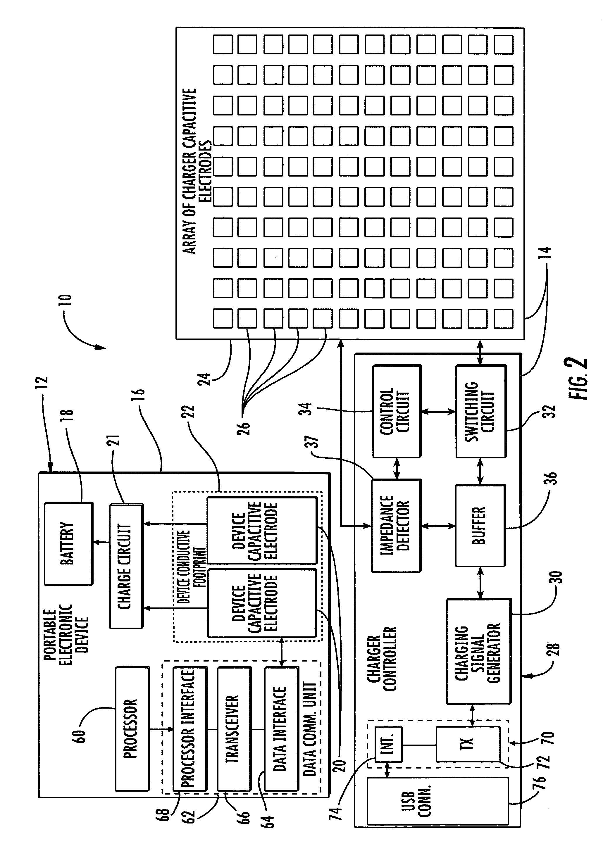
[0015] Generally, an electronic apparatus and method is disclosed for conveniently charging a portable electronic device battery while also providing secure data transfer capability. The electronic apparatus includes a portable electronic device and a charger for capacitively charging the portable electronic device. The portable electronic device comprises a housing, a device data communication unit and an associated battery carried by the housing, and at least one pair of dev...


PUM


Abstract

The electronic apparatus includes a portable electronic device and a charger for capacitively charging the portable electronic device when the portable electronic device is temporarily placed adjacent the charger. The portable electronic device includes a device data communication unit and an associated battery, and a pair of device capacitive electrodes, defining a device conductive footprint, to receive a charging signal to charge the battery. The charger includes a base having an area larger than the device conductive footprint and able to receive the portable electronic device thereon in a plurality of different positions, and an array of charger capacitive electrodes carried by the base. A charger controller selectively drives only the charger capacitive electrodes within the device conductive footprint with a charging signal to capacitively charge the battery. A charger data communication unit communicates with the device data communication unit via the charger capacitive electrodes and device capacitive electrodes, e.g. by modulating data onto the charging signal.

Description

FIELD OF THE INVENTION [0001] The invention relates to the field of portable electronic devices, and, more particularly, to portable electronic devices and battery chargers therefor and associated methods. BACKGROUND OF THE INVENTION [0002] Rechargeable batteries are used to power many of today's portable electronic devices. Rechargeable batteries make the portable electronic device more mobile than a device requiring a plug-in power source and this generally adds convenience for the user. However, recharging the batteries for a portable electronic device may be an inconvenience to the user. [0003] For example, a rechargeable battery may carry a limited charge and therefore a user may have to monitor the charge level. Also, a user may have to make arrangements to provide for the charging of the batteries such as by carrying chargers and / or power cords. [0004] Compounding these inconveniences for the user is the potential increased power consumption by modern portable electronic devi...

Claims


Application Information

Patent Timeline
IPC IPC(8): H02J7/00
CPCH02J7/0044H02J7/025H02J2007/006H04B5/0012H02J2207/30H02J50/10H02J50/80Y02P70/50H04B5/22H02J50/05H02J50/90
Inventor BERSENEV, ALEXANDER
Owner MALIKIE INNOVATIONS LTD
Learn More