
Audio encoding apparatus and audio encoding method

a technology of audio encoding and audio signal, which is applied in the field of audio encoding apparatus and audio encoding method of encoding an audio signal, can solve the problems of inability to detect the change in the property of the input signal, the judgment of improperness, and the first prior art requires a large throughput, so as to reduce the decline of the sound quality, reduce the throughput, and reduce the effect of the sound quality

Inactive Publication Date: 2007-05-24
FUJITSU LTD
View PDF10 Cites 11 Cited by
  • Summary
  • Abstract
  • Description
  • Claims
  • Application Information

AI Technical Summary

Benefits of technology

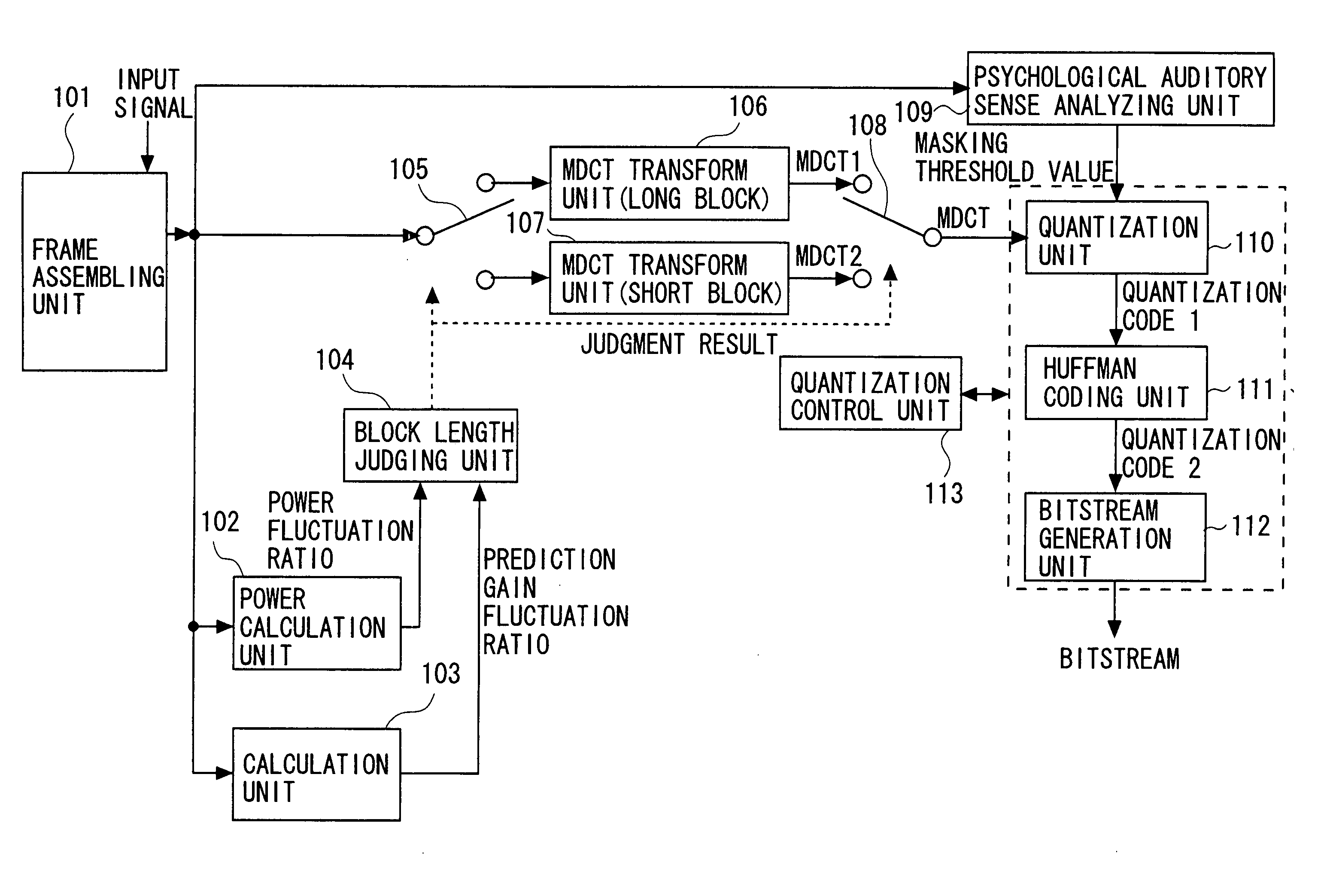
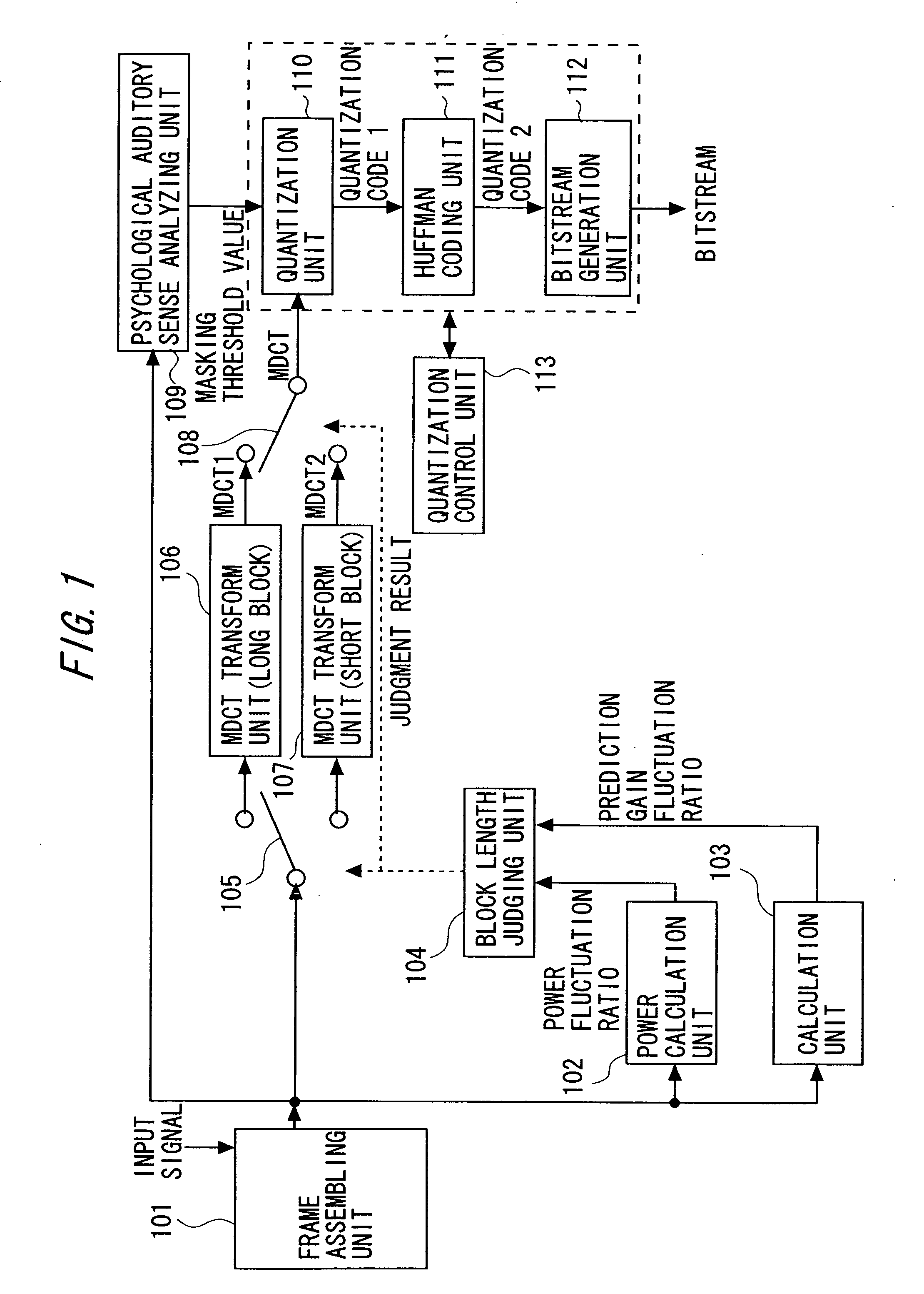
The present invention provides an audio encoding apparatus and method that can select the proper block length for encoding based on the power fluctuation ratio and prediction gain fluctuation ratio, reducing the amount of throughput needed while maintaining good audio quality. The apparatus includes a power calculation unit to calculate the power fluctuation ratio and a prediction gain fluctuation ratio based on the input signal. A block length judging unit selects between a long block mode and a short block mode based on the power fluctuation ratio and prediction gain fluctuation ratio. A threshold value determining unit changes the threshold value for judging the block length based on the selecting result of the block length judging unit. The apparatus can generate a bitstream using the modified discrete cosine transform and Huffman coding, and can adjust the quantization control unit based on the total number of bits in the bitstream. The technical effect of the invention is to improve the efficiency of audio encoding while maintaining good audio quality.

Problems solved by technology

Subsequently, the AAC system obtains such a total bit count that a quantization error caused when transforming the MDCT spectrum into the exponent part and the mantissa part is equal to or smaller than an allowable error.
Subsequently, the AAC system makes, if the total bit count is larger than the preset bit rate, the judgment of its being improper.
Therefore, the first prior art requires a large throughput.
If the property of the input signal changes even when the power fluctuation ratio does not change, however, there might be a case in which the second prior art is incapable of detecting the change in the property of the input signal.
For instance, with a sine wave being an input, if a frequency of the sine wave changes while the power is kept constant, the second prior art is incapable of detecting a signal change point by the method using only the power fluctuation ratio.
Therefore, in this case, the second prior art is incapable of detecting the signal change.
Consequently, the sound quality is deteriorated in the second prior art.
Therefore, the first prior art has the problem that the throughput increases as compared with the case of processing by use of only the long block or the short block.
Further, the second prior art is incapable of detecting the change in the property of the signal unless the power fluctuation ratio changes even when the property of the input signal varies.
Hence, the problem of the second prior art is that there might be a case of being unable to select the proper block length.

Method used


Image

  • Audio encoding apparatus and audio encoding method
  • Audio encoding apparatus and audio encoding method
  • Audio encoding apparatus and audio encoding method

Examples


first embodiment

[0184]FIG. 4 is a diagram of a configuration in a first embodiment of the audio encoding apparatus of the present invention. In FIG. 4, a frame assembling unit 401 segments inputted signals into input signal frames (long blocks) each consisting of a predetermined sample count.

[0185] Next, an MDCT transform unit 410 for the short block, a power calculation unit 402 and an auto-correlation calculation unit 403 segment an inputted single frame into short blocks. The frame segmentation in the first embodiment will be explained with reference to FIG. 2 given above. FIG. 2 is the conceptual diagram showing the example of the long block and the short block. In the example depicted in FIG. 2, one frame (long block) is segmented into four short blocks. The following discussion will be made based on this example. The first embodiment is, however, established in the same way also in the case of segmenting one frame into n-pieces of short blocks (n is a non-negative integer).

[0186] (1) At fir...

second embodiment

[0211]FIG. 6 is a diagram of a configuration in a second embodiment of the audio encoding apparatus of the present invention. A difference of the second embodiment from the first embodiment is a scheme of dynamically changing the threshold value THPwith respect to the power fluctuation ratio and the threshold value THG with respect to the prediction gain fluctuation ratio. The operations other than this scheme are common to those in the first embodiment and are therefore omitted in their explanations.

[0212] Generally, in many cases, the short block is selected in an abruptly changing area as in an attack sound etc. The attack sound is large of amplitude of the MDCT spectrum over a broad frequency range. Hence, the attack sound requires a tremendous quantization bit count in the case of encoding.

[0213] If the short block is consecutively selected, there might be a case in which the sound quality extremely declines due to deficiency of the quantization bit count. Therefore, such a c...

third embodiment

[0227] Next, a third embodiment of the audio encoding apparatus of the present invention will be described. A configuration in the third embodiment is the same as in the first embodiment shown in FIG. 4. A different point of the third embodiment from the first embodiment is, however, such that the prediction gain fluctuation ratio is obtained on a frame-by-frame basis (with a frame unit). Namely, a scheme of the third embodiment is that a single block is built up by employing a predetermined number of blocks for the power calculation, and the prediction gain fluctuation ratio of this single block is calculated.

[0228] In the first embodiment, the LPC analysis is conducted for every short block. The first embodiment is therefore capable of precisely calculating the prediction gain fluctuation ratio. In the first embodiment, however, the throughput rises because of an increased execution count of the LPC analysis. In the third embodiment, the LPC analysis is conducted once for one lon...


PUM


Abstract

An audio encoding apparatus comprising: a power calculation unit that calculates a power fluctuation ratio based on the input signal; a calculation unit that calculates a prediction gain fluctuation ratio based on the input signal; and a block length judging unit that selects one of encoding using a long block mode segmenting an input signal into frames each consisting of a predetermined number of samples and encoding each of the frames, and encoding using a short block mode segmenting each of the frames into short blocks and encoding each of the short blocks, based on the power fluctuation ratio and the prediction gain fluctuation ratio.

Description

CROSS-REFERENCE TO RELATED APPLICATION [0001] This is a continuation of Application PCT / JP2004 / 010416, filed on Jul. 22, 2004, now pending, the contents of which are herein wholly incorporated by reference.BACKGROUND OF THE INVENTION [0002] 1. Field of the Invention [0003] The present invention relates to an audio encoding apparatus and an audio encoding method of encoding an audio signal. [0004] 2. Description of the Related Art [0005] Over the recent years, communication fields such as the Internet and satellite broadcasting have rapidly spread. Further, AV (Audio Visual) devices such as a DVD have also spread. With the spread thereof, there is increasingly a demand for audio encoding that efficiently compresses the audio signals. A mainstream type of audio encoding apparatus in recent years is an adaptive transform audio encoding apparatus that utilizes an auditory sense characteristic of the human being. A basic encoding process of the adaptive transform audio encoding apparatus...

Claims


Application Information

Patent Timeline
Patent Type & Authority Applications(United States)
IPC IPC(8): G10L19/12G10L19/025G10L19/00
CPCG10L19/0212G10L19/022G10L19/025
Inventor SUZUKI, MASANAOTSUCHINAGA, YOSHITERUSHIRAKAWA, MIYUKI
Owner FUJITSU LTD
Learn More