
Method and System of Control Signaling for a Wireless Access Network

a wireless access network and wireless access technology, applied in the field of wireless communication, can solve the problems of network problems, wireless specific interfaces being integrated into call agents or servers of control planes for signaling, etc., and achieve the effect of enhancing interoperability

Inactive Publication Date: 2007-05-24
CISCO TECH INC
View PDF20 Cites 10 Cited by
  • Summary
  • Abstract
  • Description
  • Claims
  • Application Information

AI Technical Summary

Benefits of technology

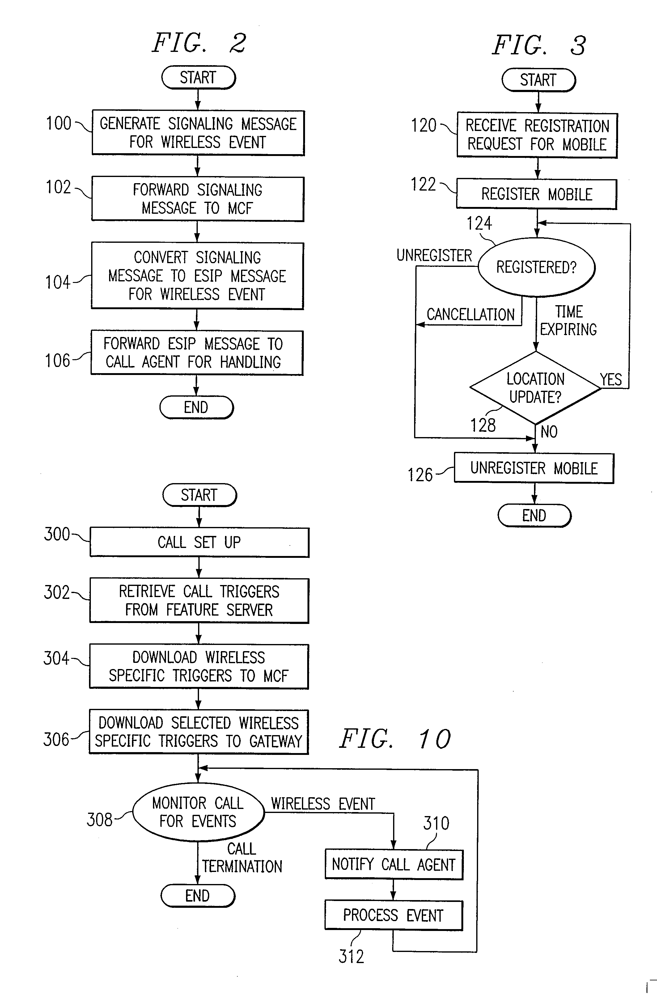
[0010] Another technical advantage of the present invention includes providing an improved mobility manager, or mobility control function (MCF) for the control plane of the communication network. In particular, the MCF is integrated or interfaced with a call agent or call server to provide a common control network across wireless and wireline networks. The MCF may use an extended (SIP) interface to communicate with the call agent and translate between the wireless-specific interface and the extended SIP interface. Because SIP is a widely-used protocol, wireless-specific extensions can be standardized across networks for enhanced interoperability.
[0011] Still another technical advantage of the present invention includes supporting new location-based or other wireless-specific services with the call agent. For example, using extended SIP, the call agent may support call establishment, mobility management, registration and location updates for mobile devices in a wireless access network. Location-based services may provide the location of a mobile user to a called party, a calling party or business or other establishment in the area of the mobile user.
[0012] The various embodiments of the present invention may include all, some or none of the enumerated advantages. Furthermore, other advantages of the present invention will be readily apparent to one skilled in the art from the following figures, descriptions and claims.

Problems solved by technology

Integration of such wireless specific interfaces into call agents or servers of the control plane for signaling between the control plane and the access network is problematic because the call agent / servers typically utilize session initiation protocol (SIP) for signaling and standardized SIP does not support wireless-specific functionality.

Method used


Image

  • Method and System of Control Signaling for a Wireless Access Network
  • Method and System of Control Signaling for a Wireless Access Network
  • Method and System of Control Signaling for a Wireless Access Network

Examples


Embodiment Construction

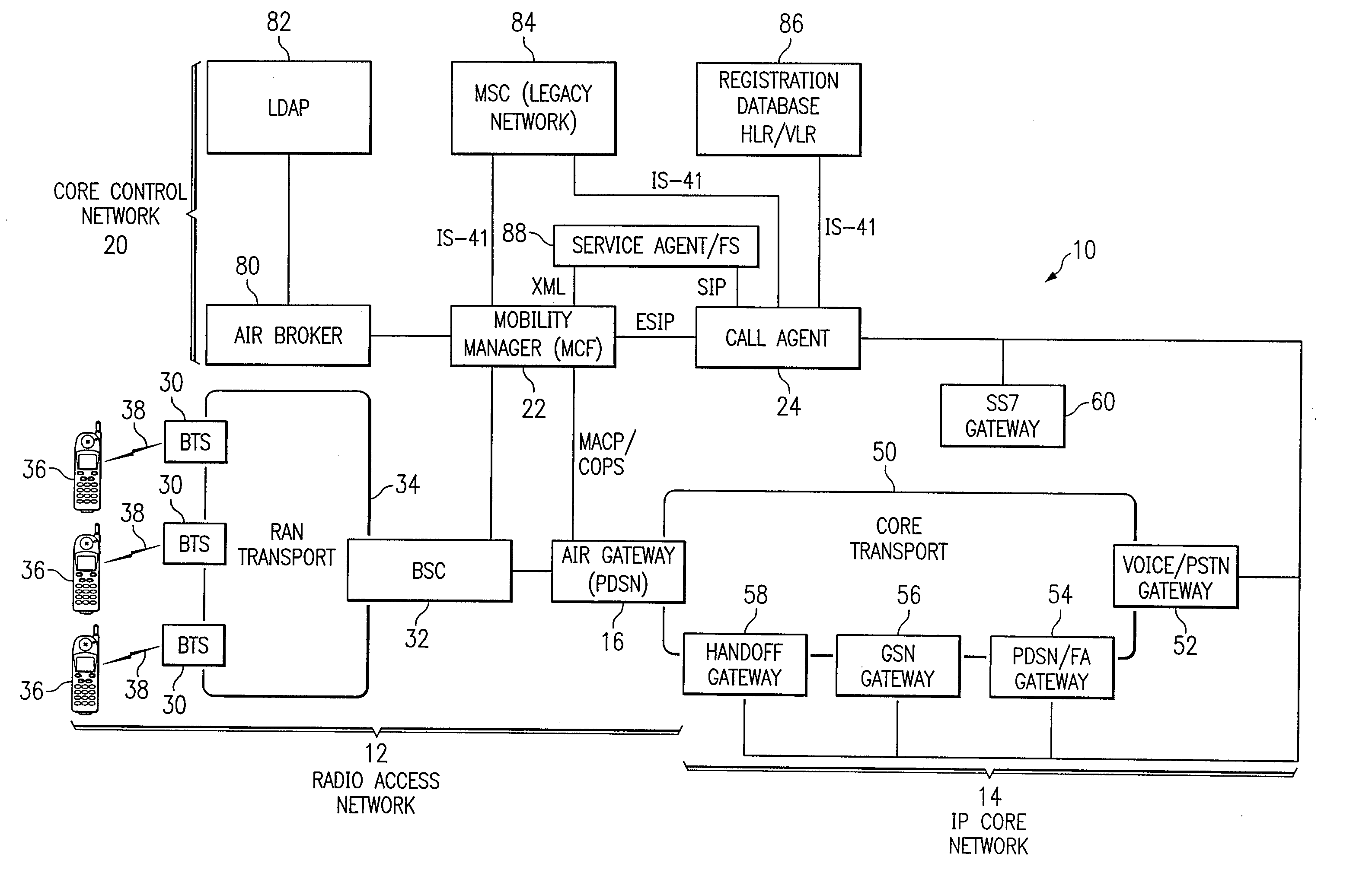
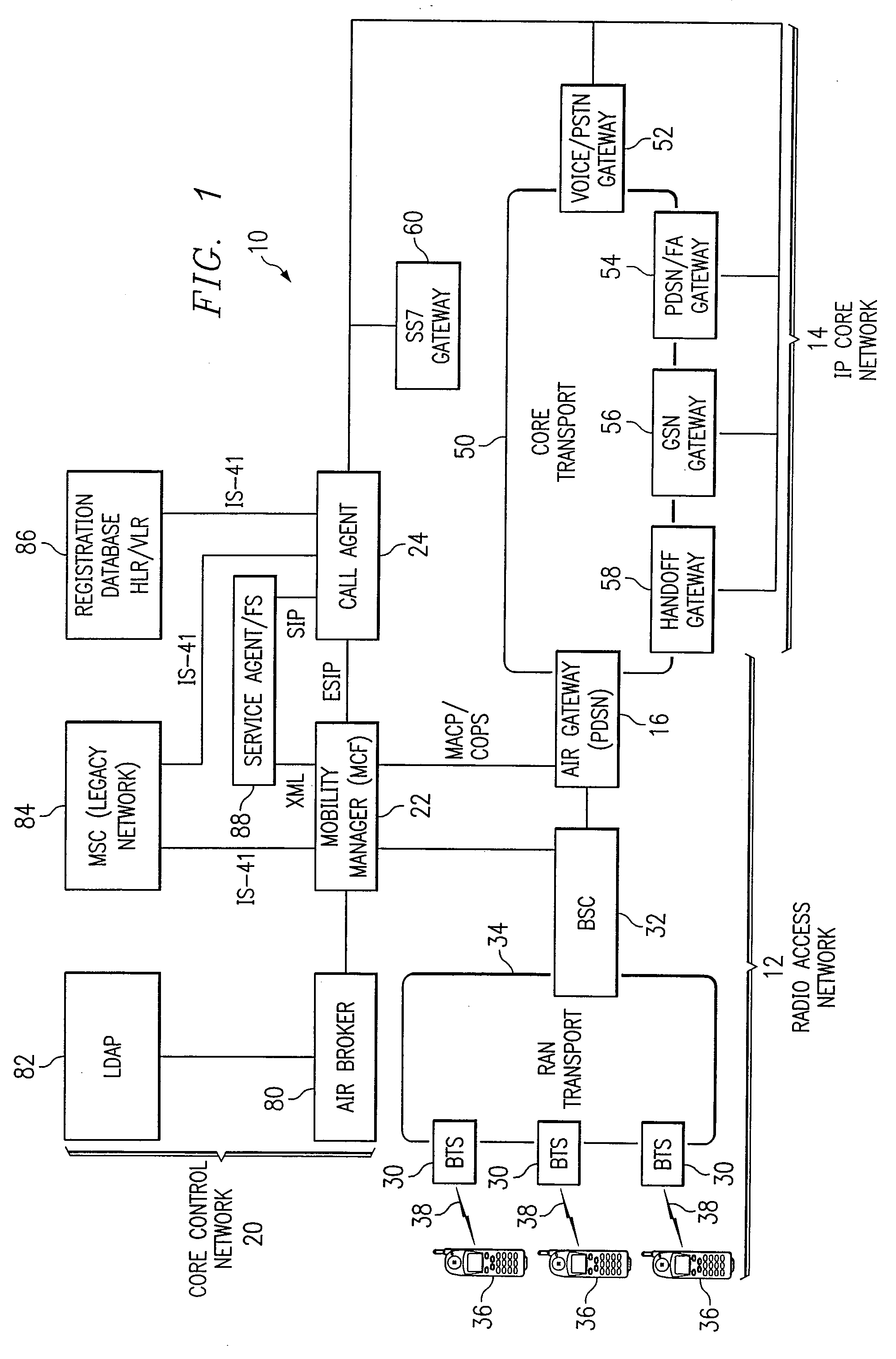
[0026]FIG. 1 illustrates a communication network 10 in accordance with one embodiment of the present invention. In this embodiment, the communication network 10 includes a cellular wireless network in which terrestrial wireless transmissions originate in geographically delimited cells. It will be understood that the present invention may be used in connection with satellite and other suitable wireless networks.

[0027] Referring to FIG. 1, the communication network 10 includes a wireless network 12 connected to a wireline network 14 through an air gateway 16 that separates signaling and bearer traffic and converts traffic between wireless and wireline formats. The air gateway may comprise a packet data serving node (PDSN) for CDMA or CDMA 2000 or comprise a signaling gateway server node (SGSN) for universal mobile telecommunications system (UMTS) or other suitable node. In the CDMA embodiment, the PDSN 16 may have a router that directs traffic in the bearer plane between the wireless...


PUM


Abstract

A method and system of control signaling for a wireless access network includes receiving from a wireless access network a signaling message for a mobile device. The signaling message is in a wireless-specific format. The signaling message is converted to a native format of a call agent to generate a call agent message. The call agent message comprises wireless-specific information of the signaling message.

Description

RELATED PATENT APPLICATIONS [0001] This application is a continuation of U.S. application Ser. No. 09 / 907,626 filed Jul. 18, 2001 and entitled “Method and System of Control signaling for a Wireless Access Network”. [0002] This application is related to U.S. patent application Ser. No. 09 / 907,785 entitled “Method and System for Providing Supplementary Services for a Wireless Access Network,” and U.S. patent application Ser. No. 09 / 908,081 entitled “Method and System for Providing Wireless-Specific Services for a Wireless Access Network,” all filed on Jul. 18, 2001.TECHNICAL FIELD OF THE INVENTION [0003] This invention relates generally to the field of wireless communications, and more particularly to a method and system of control signaling for a wireless access network. BACKGROUND OF THE INVENTION [0004] Traditional wireless networks include a number of base transceiver stations (BTSs) and one or more mobile switching centers (MSCs) and base station controllers (BSCs). The BTSs each...

Claims


Application Information

Patent Timeline
Patent Type & Authority Applications(United States)
IPC IPC(8): H04L12/66
CPCH04W4/18H04W64/00H04W74/00H04W76/02H04W80/00H04W76/10
Inventor DANTU, RAMANAMURTHYCHIANG, SHIHLUNGYIN, HAOCHIHKACHHLA, RASIK
Owner CISCO TECH INC
Learn More