
Interlocking structure for floor panel

a technology of interlocking structure and floor panel, which is applied in the direction of walls, constructions, building components, etc., can solve the problems of still sinking or opening of the joints

Inactive Publication Date: 2007-05-24
ZHANG WEIXIANG
View PDF6 Cites 26 Cited by
  • Summary
  • Abstract
  • Description
  • Claims
  • Application Information

AI Technical Summary

Benefits of technology

[0006] The floor panel made in this way, just because there is the interlocked gear shaped tooth (tongue) on the vertical section of the tongue and groove connection. This interlocking increased the bearing capacity of floor panel from vertical acting force. And the abutting joint of panels is also improved obviously. Secondly, the new construction of tongue and groove in accordance with the invention benefits the surface area of panel without loss when cutting panel, so compare with the prior art having surface with loss cutting, it enhanced the utilization factor of wood or floor material. Furthermore, the design of the interlocking structure benefits the hand worked laying of floor panel directly without tools when two adjoining panels are jointed together. It made the laying of floor panel simple and saves the man-hour relatively. Besides, this utility model is useful and helpful to processing panel in vertical direction and laying precision of panel, as well as preventing the breakage of joint and distortion of floor panel.

Problems solved by technology

But it was found in service use that the joint still would be sink or open when there is stronger acting force on the floorboard.

Method used


Image

  • Interlocking structure for floor panel
  • Interlocking structure for floor panel
  • Interlocking structure for floor panel

Examples


first embodiment

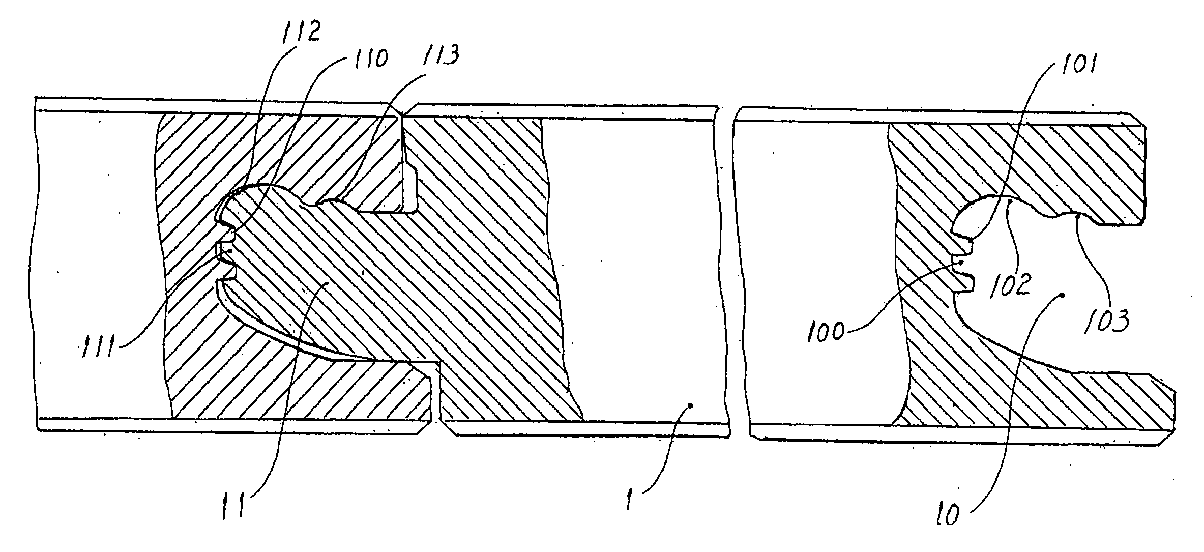
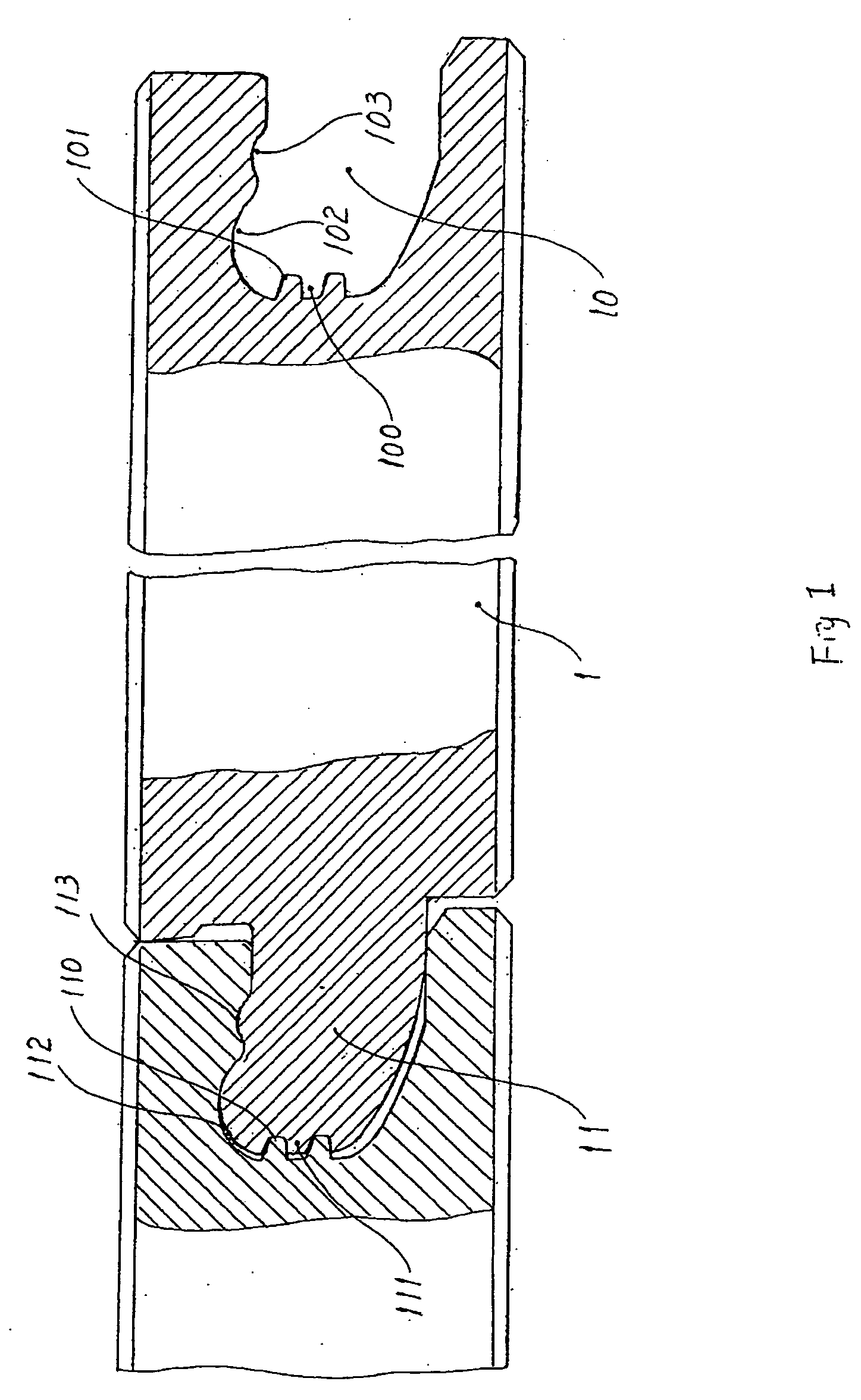
[0008]FIG. 1 is a schematic drawing of the cross-section of first embodiment of the present application.

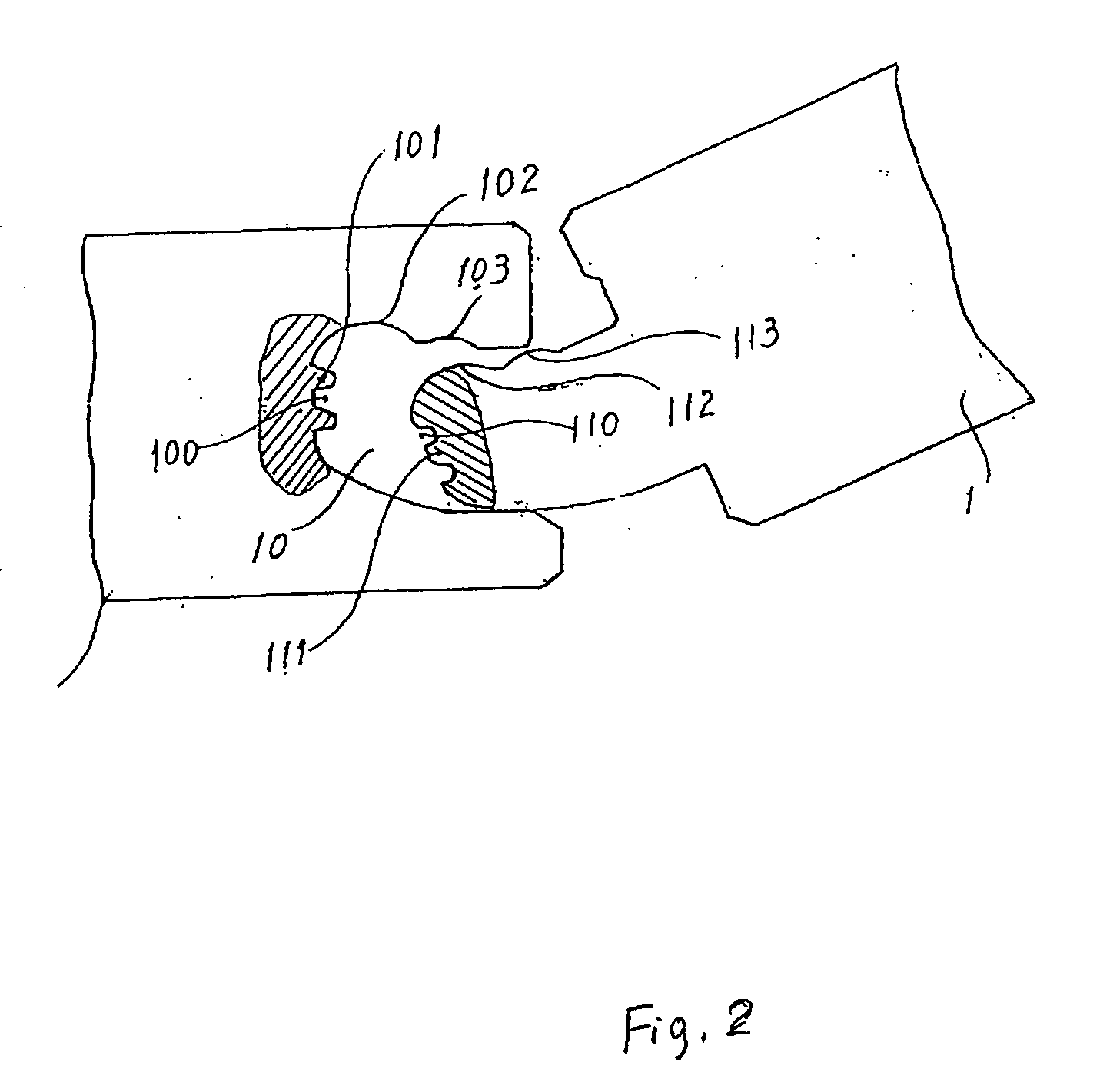
[0009]FIG. 2 is the schematic drawing of the cross-section of assembly of present application used in first embodiment of FIG. 1.

second embodiment

[0010]FIG. 3. is a schematic drawing of the cross-section of the present application.

third embodiment

[0011]FIG. 4. is a schematic drawing of third embodiment of the present application.

DETAILED DESCRIPTION OF THE REFERENCED EMBODIMENTS

[0012] This is the further explanation combine with the accompanying drawings for embodiments. As shown in the accompanying drawings, FIG. 1 and FIG. 2, the flange 11 and recess 10 are made in the both edges of floor panel 1. On the vertical side of flange 11 of floor panel, the tooth (tongue) 111 and the groove 110 positioned both sides of the tooth 111, whose section configuration is trapezia, are made on the suitable place. On the other edge of the floor panel, the groove 100 in trapezia form was made in recess 10 of floor panel to corresponding with tooth (tongue) 111, and the two trapezia shaped tooth 101 to interlock with the trapzia shaped groove (tooth space) 110. To ensure the adjoining of the floor panel are stronger and tighter, the arc shaped hump 112, 113 and the depression 102, 103 are made on the connecting aspect of the flange 11 and ...


PUM


Abstract

This utility model is a new interlocking structure for floor panel. The new interlocking structure for floor panel in accordance with the invention comprising floor panels; one panel edge having an upwardly curved flange, having at least one tooth, formed at it end and at least one hump and depression along its one top surface; the adjacent panel has a generally correspondingly shaped recess to receive the flange, the sectional configuration of tooth is trapezia. The floor panel made in this way, just because there is the interlocked gear shaped tongue on the vertical section of the tongue and groove connection. This interlocking increased the bearing capacity of floor panel from vertical acting force. And the abutting joint of panels is also improved obviously. It is useful and helpful to processing panel in vertical direction and laying precision of panel, as well as preventing the breakage of joint and distortion of floor panel.

Description

FIELD OF THE INVENTION [0001] This utility model relates to a interlocking structure for floor panel, especially it relates to a new tongue and groove structure for floor panel. BACKGROUND OF THE INVENTION [0002] The fortified wooden floor is the new developed building materials in recent years. Compare with the solid wood floor, it is concerned with and shows broad useful prospect just because it has the characters of high quality and inexpensive, steady and durable, simple process of laying, low cost of construction and dismountable. The fortified floor depends on connected panel pieces with the tongue and groove on all edges. Moreover, it is laid on the floor directly, not set the keel. So, the shape and structure of the interlocking structure is very important to the floorboard connection and the quality of the laying. The interlocking structure consists of the tongue and grove. Furthermore, the section configuration of the tongue and grove should be corresponding and occlusive....

Claims


Application Information

Patent Timeline
IPC IPC(8): E04B2/00
CPCE04F15/04E04F2201/0153E04F2201/025E04F2201/028E04F2201/041
Inventor ZHANG, WEIXIANG
Owner ZHANG WEIXIANG
Learn More