
Optically powered and optically data-transmitting wireless intraocular pressure sensor device

a sensor device and optical data technology, applied in the field of medical devices and, can solve the problems of not being used as a standard method of measuring, the contact ones cannot be administered in the physician's office, and the non-standard use of micromachined devices, so as to avoid/reduce artifacts

Inactive Publication Date: 2007-05-17
CALIFORNIA INST OF TECH +1
View PDF13 Cites 33 Cited by
  • Summary
  • Abstract
  • Description
  • Claims
  • Application Information

AI Technical Summary

Benefits of technology

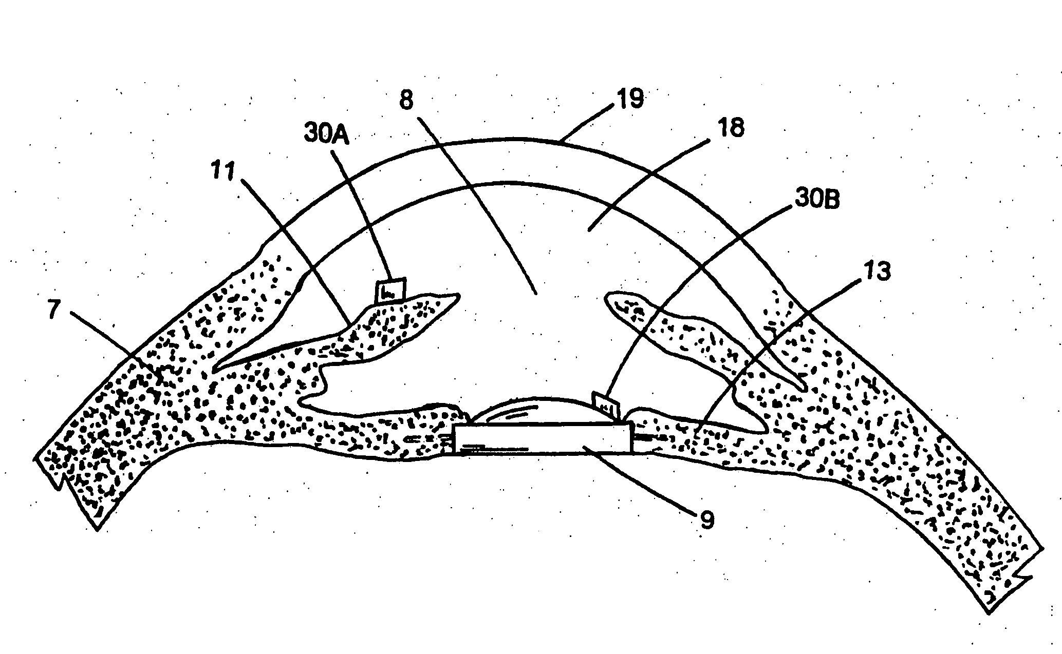
The present invention provides an optically powered and optically data-transmitting wireless pressure sensor device for detecting excessive intraocular pressure above a predetermined threshold pressure. The device comprises a pressure switch that is sized and configured to be placed in the anterior chamber of an eye, wherein the pressure switch is activated when the intraocular pressure is higher than the predetermined threshold pressure. The device can be powered by a solar cell system or a battery, and can be placed on the iris of an eye or on an intraocular lens or on a glaucoma tube for external data readout. The device can record the time, date, and duration of activity, and can be optically activated and read by an external instrument. The invention provides a means for the intraocular pressure data to be downloaded to a computer and transmitted over the Internet to a central location such as a physician's office.

Problems solved by technology

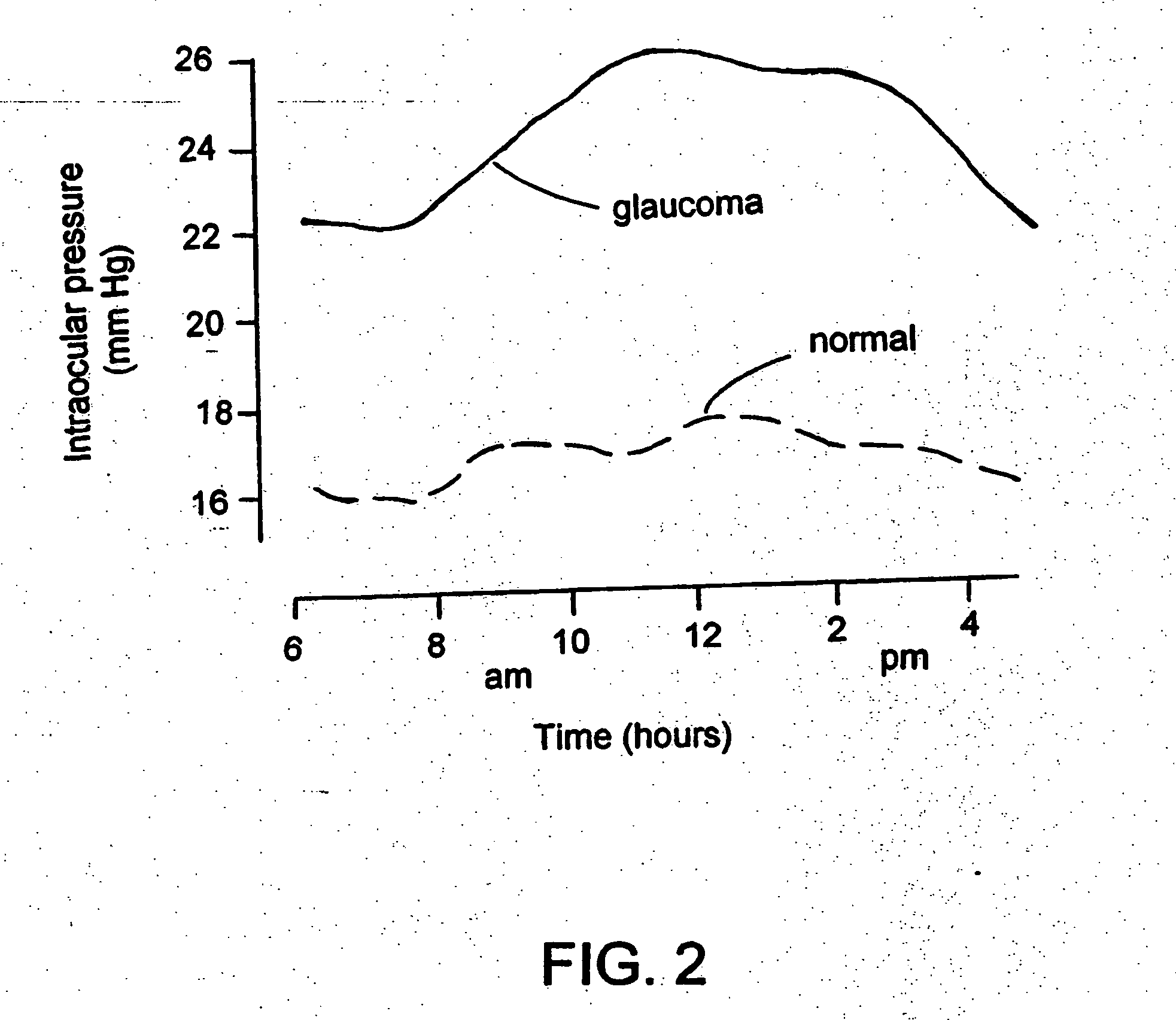
If untreated, glaucoma leads to blindness.
Both contact and non-contact tonometers are very dependent on the eye wall and corneal rigidity and can be grossly wrong because these factors are not taken into account.
In addition to the problems of imprecision with most of the external IOP measuring devices, at least the contact ones can only be administered in physicians' offices.
However, none of the micromachined devices are being used as a standard method to measure IOP because they are too invasive to be implanted and / or have not been validated in a realistic variable pressure environment (e.g., in an animal eye).
None of the above-cited prior art discloses an optically powered and optically data-transmitting wireless intraocular pressure sensor, suitable for being implanted in the eye and for monitoring the IOP continuously or on demand.
Moreover, none of the above-cited prior art discloses a solar cell system-powered or battery-powered wireless intraocular pressure sensor.

Method used


Image

  • Optically powered and optically data-transmitting wireless intraocular pressure sensor device
  • Optically powered and optically data-transmitting wireless intraocular pressure sensor device
  • Optically powered and optically data-transmitting wireless intraocular pressure sensor device

Examples


Embodiment Construction

[0029] The preferred embodiments of the present invention described below relate particularly to an optically powered and optically data-transmitting wireless intraocular pressure sensor that can be implanted in the anterior chamber of an eye by securing it onto the peripheral iris tissue or onto an intraocular lens out of line of sight. While the description sets forth various embodiment specific details, it will be appreciated that the description is illustrative only and should not be construed in any way as limiting the invention. Furthermore, various applications of the invention, and modifications thereto, which may occur to those who are skilled in the art, are also encompassed by the general concepts described below.

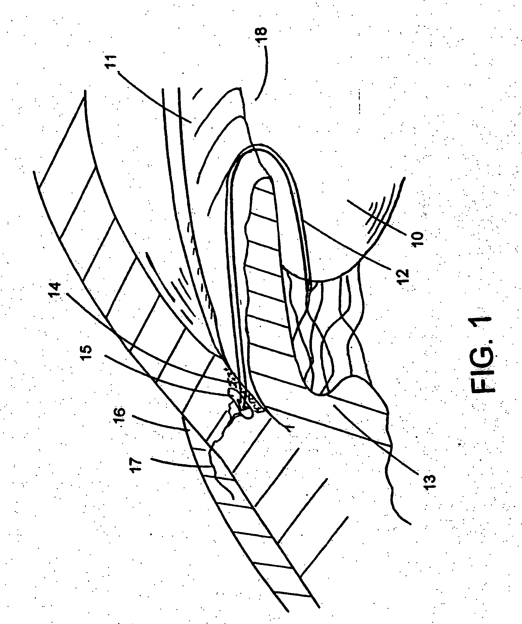
[0030]FIG. 1 illustrates a general aqueous flow 12 around the front section of an eye, showing relative anatomical locations of the trabecular meshwork 14, the anterior chamber 18, and Schlemm's canal 15. The cornea 19 (FIG. 6) is a thin transparent tissue that ...


PUM


Abstract

An optically powered and optically data-transmitting wireless intraocular pressure sensor device for detecting excessive intraocular pressure above a predetermined threshold pressure, comprising a pressure switch that is sized and configured to be placed in an eye, wherein said pressure switch is activated when the intraocular pressure is higher than the predetermined threshold pressure. In one embodiment, the pressure sensor device is a micro electromechanical system.

Description

CROSS-REFERENCE TO RELATED APPLICATION [0001] The present application claims the benefits of provisional application Ser. No. 60 / 419,014, filed Oct. 16, 2002, and provisional application Ser. No. 60 / 446,403, filed Feb. 11, 2003; the entire contents of which are incorporated herein by reference.FIELD OF THE INVENTION [0002] The present invention generally relates to an improved medical device and methods for sensing the elevated pressure in organs of the human body. More particularly, the present invention relates to an intraocular pressure sensor that is accurate and small enough to be implantable in the eye to continuously or on demand monitor the intraocular pressure in ocular hypertensives and patients with glaucoma, thus helping to prevent the onset of damage from glaucoma and to monitor effects of glaucoma therapy. BACKGROUND OF THE INVENTION [0003] Glaucoma is a disease affecting millions of people in the US alone every year. Elevated intraocular pressure (IOP), the most commo...

Claims


Application Information

Patent Timeline
Patent Type & Authority Applications(United States)
IPC IPC(8): A61B3/16
CPCA61B3/16
Inventor FINK, WOLFGANGYANG, EUI-HYEOKHISHINUMA, YOSHILEE, CHOONSUPGEORGE, THOMASHUMAYUN, MARK
Owner CALIFORNIA INST OF TECH
Learn More