
Treating a SiGe layer for selective etching

Inactive Publication Date: 2007-05-17
S O I TEC SILICON ON INSULATOR THECHNOLOGIES
View PDF36 Cites 24 Cited by
  • Summary
  • Abstract
  • Description
  • Claims
  • Application Information

AI Technical Summary

Benefits of technology

[0011] The aim of the invention it to provide a solution which can facilitate removal or lifting-off by selective etching of a layer of silicon-germanium (SiGe) subsisting above a layer of strained silicon, and which is thus reliable while preserving the layer of strained silicon from excessive over-etching.

Problems solved by technology

This excessive prolongation of etching leads to the formation of a rough post-etch surface, or even to the formation of HF defects, and lifting off or removing the whole transitional zone containing germanium leads to over-etching of the layer of strained silicon.

Method used


Image

  • Treating a SiGe layer for selective etching
  • Treating a SiGe layer for selective etching
  • Treating a SiGe layer for selective etching

Examples


Embodiment Construction

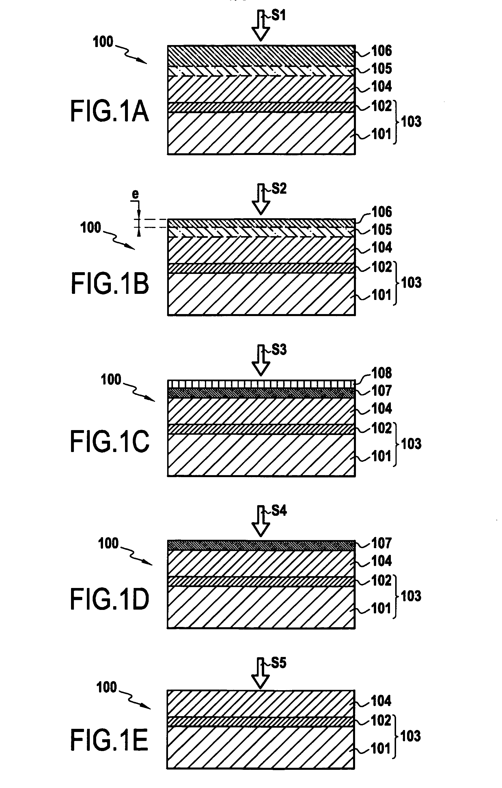
[0020] The method of the present invention is generally applicable to any layer or remainder of a layer of silicon-germanium (Si1-xGex where 0≦x≦1) subsisting above a layer of strained silicon and which is to be eliminated by selective etching. As a result, the present invention is of particular application in the fabrication of sSOI type wafers using the SMART-CUT® technique.

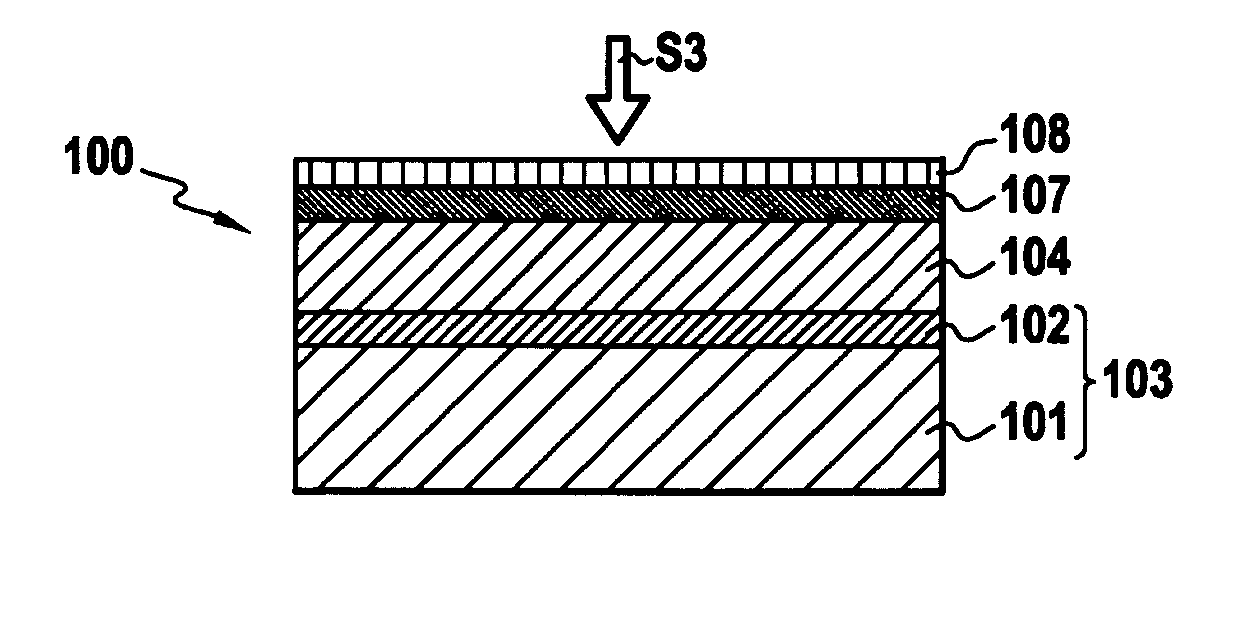
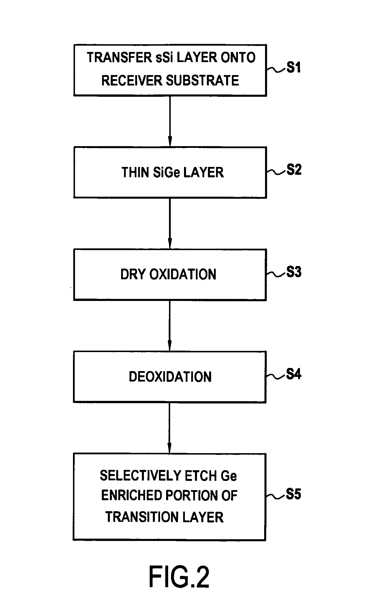
[0021] The layer of SiGe is intended to be lifted by selective chemical etching to expose the strained silicon layer on which it is disposed. This method comprises, prior to selective etching, a step of oxidation of the SiGe layer to form a surface layer of silicon oxide and a lower layer with a high and homogeneous concentration of germanium. The lower layer has a germanium concentration or content which is higher than that of the layer of SiGe prior to oxidation.

[0022] The step of oxidation of the SiGe layer allows a layer of silicon oxide containing very little germanium and a subjacent layer which is enri...


PUM


Abstract

The invention relates to a method of lifting a layer of silicon-germanium of formula Si1-xGex (0≦x≦1) disposed on a layer of strained silicon. The layer of silicon-germanium is intended to be lifted by selective chemical etching to expose the strained silicon layer. Prior to selective etching step, the method includes a step of oxidation of the layer of silicon-germanium to form a superficial layer of silicon oxide and an enriched lower layer having a concentration (x) of germanium which is greater than that of the layer of silicon-germanium. The layer of silicon oxide is then eliminated by a deoxidation step.

Description

BACKGROUND [0001] The present invention relates to the fabrication of wafers, in particular those of the strained silicon on insulator (sSOI) type. [0002] Several techniques exist for producing such wafers. One of the best current techniques for the fabrication of sSOI type wafers is that of producing an active layer of strained silicon (abbreviated to sSi) using SMART-CUT® technology to produce the desired heterostructure. An example of the use of SMART-CUT® technology applied to the production of SOI wafers has been described in United States patent U.S. Pat. No. 5,374,564 or in the article by A. J. Auberton-Hervé et al entitled “Why can SMART-CUT® change the future of microelectronics?”, Int. Journal of High Speed Electronics and Systems, Vol. 10, No. 1, 2000, p. 131-146. Examples of the use of SMART-CUT® technology applied to the specific production of sSOI type wafers are described in United States patent application U.S. Pat. No. 6,953,736 and International patent application ...

Claims


Application Information

Patent Timeline
IPC IPC(8): H01L21/30H01L21/311H01L21/31
CPCH01L21/76254
Inventor DELATTRE, CECILEDAVAL, NICOLAS
Owner S O I TEC SILICON ON INSULATOR THECHNOLOGIES
Learn More