
Tail-driven screw fastener for use in tamper-resistant and decorative applications

a tail-driven screw and decorative technology, applied in the direction of screws, fastening devices, etc., can solve the problems of not being able to easily come off, being unusual and difficult to improvise, and being aware of the limitations of the options currently commercially available, so as to improve the product's commercial viability, add to the cost of setup, and clean the

Inactive Publication Date: 2007-05-17
FITCH CHRISTOPHER MILTON
View PDF5 Cites 17 Cited by
  • Summary
  • Abstract
  • Description
  • Claims
  • Application Information

AI Technical Summary

Benefits of technology

[0013] D. Fasteners can be manufactured to existing standards with existing capabilities at minimal, if any, additional set up cost.
[0014] My invention takes an ordinary machine screw and reorganizes its functional components in a new, unobvious, and useful way. Normal machine screws are driven from their heads into their working positions. My invention describes a means and a method to drive machine screws from their tails into position and use their heads for other purposes than providing a torqueable access. By torqueable access I mean a recess or projection shaped to receive a matingly shaped member on a driving tool. In the same fashion that the female driving access of a set screw is recessed into its threaded shaft, my invention features a female driving access in the threaded shaft of its tail, or insertion, end. Alternatively, the access can be shaped in relief, creating a male torqueable access. Any drive style that is currently available or may in the future be available that is appropriate for set screws, therefore, would be appropriate for similar reasons in my invention. Currently available drive styles for such purpose include, but are not limited to, hex (or Allen), slotted, square (Robertson), or star-shaped drives (like Torx TM or Torx Plus TM).
[0015] My invention requires no significant changes in existing manufacturing technology to be made commercially available. The fact that my invention can be manufactured on existing equipment to existing standards, and satisfies existing needs is a major advantage in a fast-paced marketplace and adds to its status as a commercially viable product.
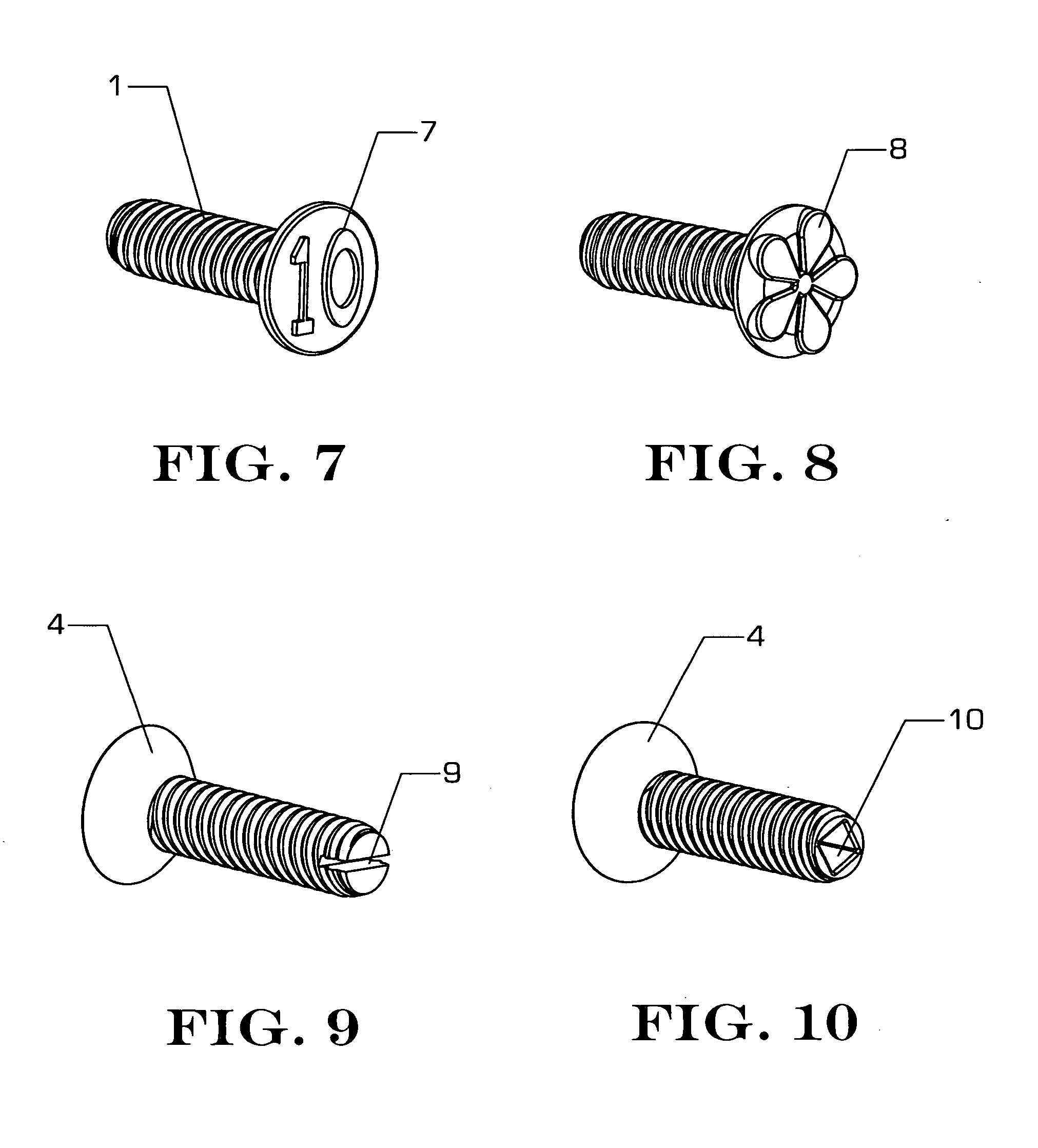
[0016] Not only can tail-driven fasteners present a blank face to the tamper-tempted individual, but having been relieved of their function as driving members, their faces are free to perform other duties. Screws often present an aesthetic challenge to engineers and designers. Given a design objective of having an assembly that has a clean look, screw heads can often be viewed negatively if they are too visible. Two preferred embodiments of my invention allow the possibility of screw heads that are perfectly clean in appearance, with a polished look, either flat-headed or round-headed with no indentations or recesses. Such screw heads would present a distinguished, elegant appearance and could very well be seen as decorative elements in their own right. Furthermore, the possibility is created to make screw heads decorative in any style or shape or material whatsoever. Some design ideas that come to mind are rounded cones, pyramids, stars, flowers, stamped or molded, etched or printed designs, or blank versions of otherwise standard screw head shapes.
[0017] Beyond serving a decorative function, unusual head designs, such as those above described, can add the further benefit of camouflaging the screws. Screws can be made with specially designed heads that match existing patterns on surfaces, for example. Or they can simply pose as ornaments themselves without betraying their hidden functional purpose. Another preferred embodiment is to number the heads of the screws, so that parts can be labeled, or assembly order can be established, or so that individual screws can be kept organized during servicing or manufacture, for example, or for any other reason. Screw heads can be etched or printed with logos, color-coded, or provide a surface for custom alteration and individual expression.
[0018] Once assembled into its component, the head of the fastener can be shaped, ground, polished, painted, etc., as if it were part of the surface of the component into which it has been assembled, with no loss of utility. Fasteners with torqueable access in their heads might lose that access if they were ground, shaped, or painted. With my invention, the drive access would remain intact, protected, and unaffected at the tail end of the screw. Grinding and polishing or painting the head of a machine screw would allow it to blend seamlessly into the background component. This would have usefulness not only for security, but also in any application in which a seamless surface is desired, such as the aerospace industry, marine industry, and for high-end design or architectural components.

Problems solved by technology

As I was involved in a project that required tamper-resistant screws, I became aware of the limitations of the options that are currently commercially available.
The first involves a driver shape that is unusual and hard to improvise.
These caps are designed to be driven on easily with a hammer blow, but do not come off easily.
There have also been more complex designs of fasteners with heads that spin, or with collars that spin, or with special drivers that clamp onto special shoulders under the head.
For instance, Kreider 3,041,912 and Wing 2,940,495 describe fastening systems with cooperating members such as grommets or frangible portions with which those inventions are primarily concerned and do not teach any advantages to head design for tamper resistance, labeling or decoration.
Salz 3,329,057 and Pumphrey 2,388,658 both disclose a slot at the tail end of their fasteners, but for Pumphrey, its purpose is specifically for turning his fastener 90 degrees to engage its head into a square hole and does not teach anything about driving from the tail end or tamper-resistance.
Screws often present an aesthetic challenge to engineers and designers.
Given a design objective of having an assembly that has a clean look, screw heads can often be viewed negatively if they are too visible.
Fasteners with torqueable access in their heads might lose that access if they were ground, shaped, or painted.

Method used


Image

  • Tail-driven screw fastener for use in tamper-resistant and decorative applications
  • Tail-driven screw fastener for use in tamper-resistant and decorative applications
  • Tail-driven screw fastener for use in tamper-resistant and decorative applications

Examples


Embodiment Construction

—FIGS. 1 TO 3

[0038] A preferred embodiment of the present invention is illustrated in FIGS. 1 to 3. In these illustrations, an embodiment is described wherein the invention resembles a common flat head machine screw. Where it differs, however, is in the placement of the drive access. In my invention, the access for torquing, or driving, the screw is found not in the head 2 but in the tail 3, or insertion end of the screw. FIG. 1 shows a side view of the screw. FIG. 2 shows an isometric view from the head end of the screw. FIG. 3 shows an isometric view from the tail end of the screw.

[0039] The preferred embodiment has a helical thread 1 that wraps around the body of the screw in any currently or future available standard or custom industrial screw thread size. The current invention is not concerned with screw thread design per se. Likewise, my invention is not focused on the issue of material selection per se, and any material that screws can be made from generally will suffice, al...


PUM


Abstract

A threaded fastener with unique tamperproof and decorative qualities comprised of a cylindrical body with helical threads (1) in combination with a non-torqueable head (2,5,7,8) at one end and a torqueable access located on the tail, or insertion, end (3,9,10). The lack of a drive access in the head of the screw creates a tamperproof surface which can be treated decoratively (7,8), ground, polished, or painted. Although tamperproof from the head side of the screw, standard torqueable access in the tail end makes the screw nevertheless easy to remove for servicing.

Description

CROSS-REFERENCE TO RELATED APPLICATIONS [0001] This application is entitled to the benefit of Provisional Patent Application Ser. No. 60 / 735,380 filed 2005, Nov. 12 by the present inventor.FEDERALLY SPONSORED RESEARCH [0002] n / a SEQUENCE LISTING OR PROGRAM [0003] n / a BACKGROUND [0004] 1. Field of Invention [0005] This invention relates to threaded fasteners of the bolt or machine screw variety, specifically to such fasteners that have tamper-resistant or decorative functions associated with them. [0006] 2. Discussion of Prior Art [0007] As I was involved in a project that required tamper-resistant screws, I became aware of the limitations of the options that are currently commercially available. Most depend on one of the following strategies to discourage people from undoing screws. The first involves a driver shape that is unusual and hard to improvise. Examples of this type include the star-shaped drive Torx Plus TM, triangular drive, or spanner drive style screws. All of these ma...

Claims


Application Information

Patent Timeline
Patent Type & Authority Applications(United States)
IPC IPC(8): F16B25/00
CPCF16B1/0071F16B33/006F16B35/045F16B2200/95
Inventor FITCH, CHRISTOPHER MILTON
Owner FITCH CHRISTOPHER MILTON
Learn More