
Image forming apparatus

a technology of forming apparatus and forming sheet, which is applied in the direction of electrographic process apparatus, thin material processing, instruments, etc., can solve the problems of large difference in moisture absorption, easy generation of large differences, and deformation, and achieve the effect of simple structure and reliable reforming of curled shape of sh

Inactive Publication Date: 2007-05-17
CANON KK
View PDF1 Cites 11 Cited by
  • Summary
  • Abstract
  • Description
  • Claims
  • Application Information

AI Technical Summary

Benefits of technology

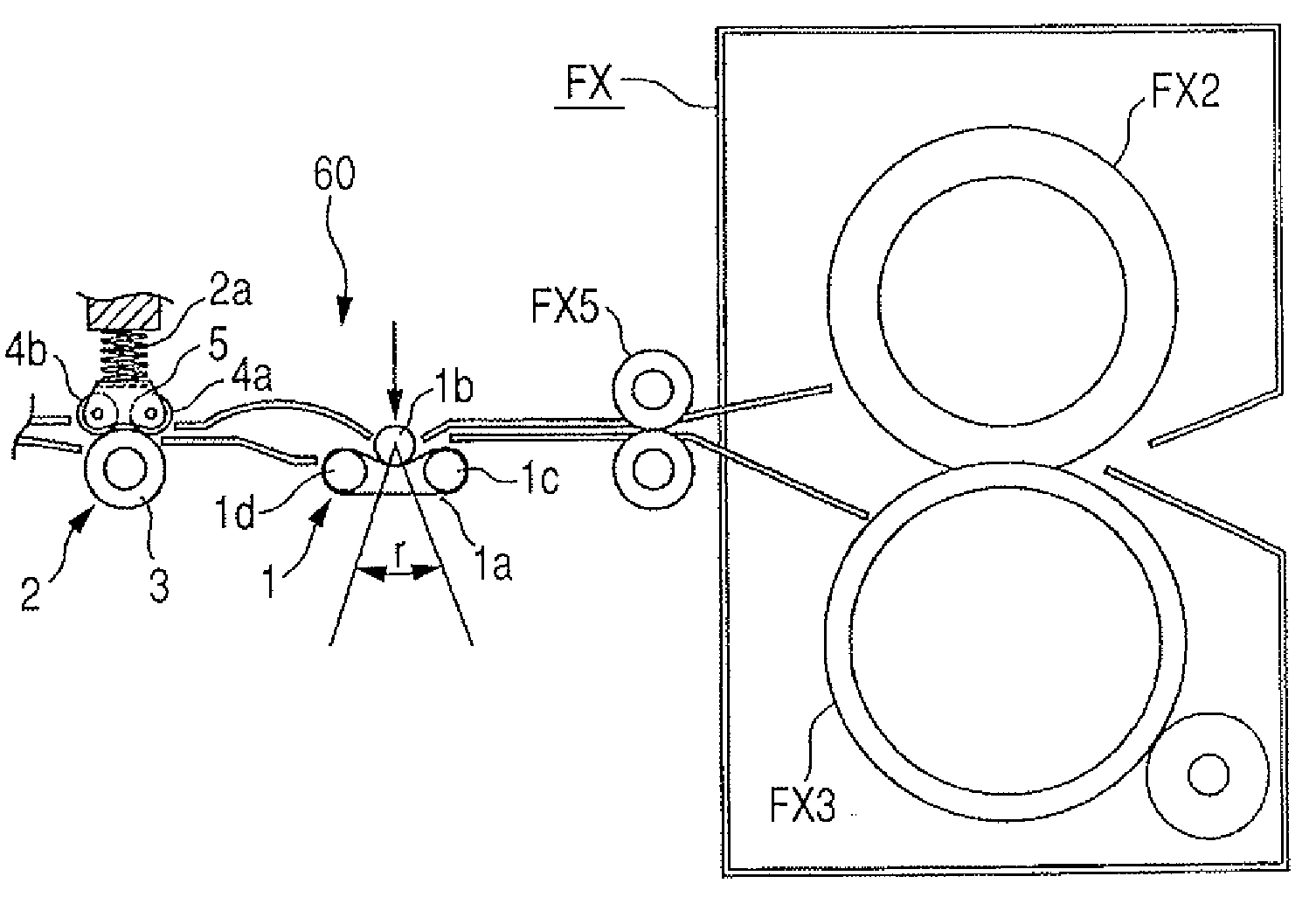
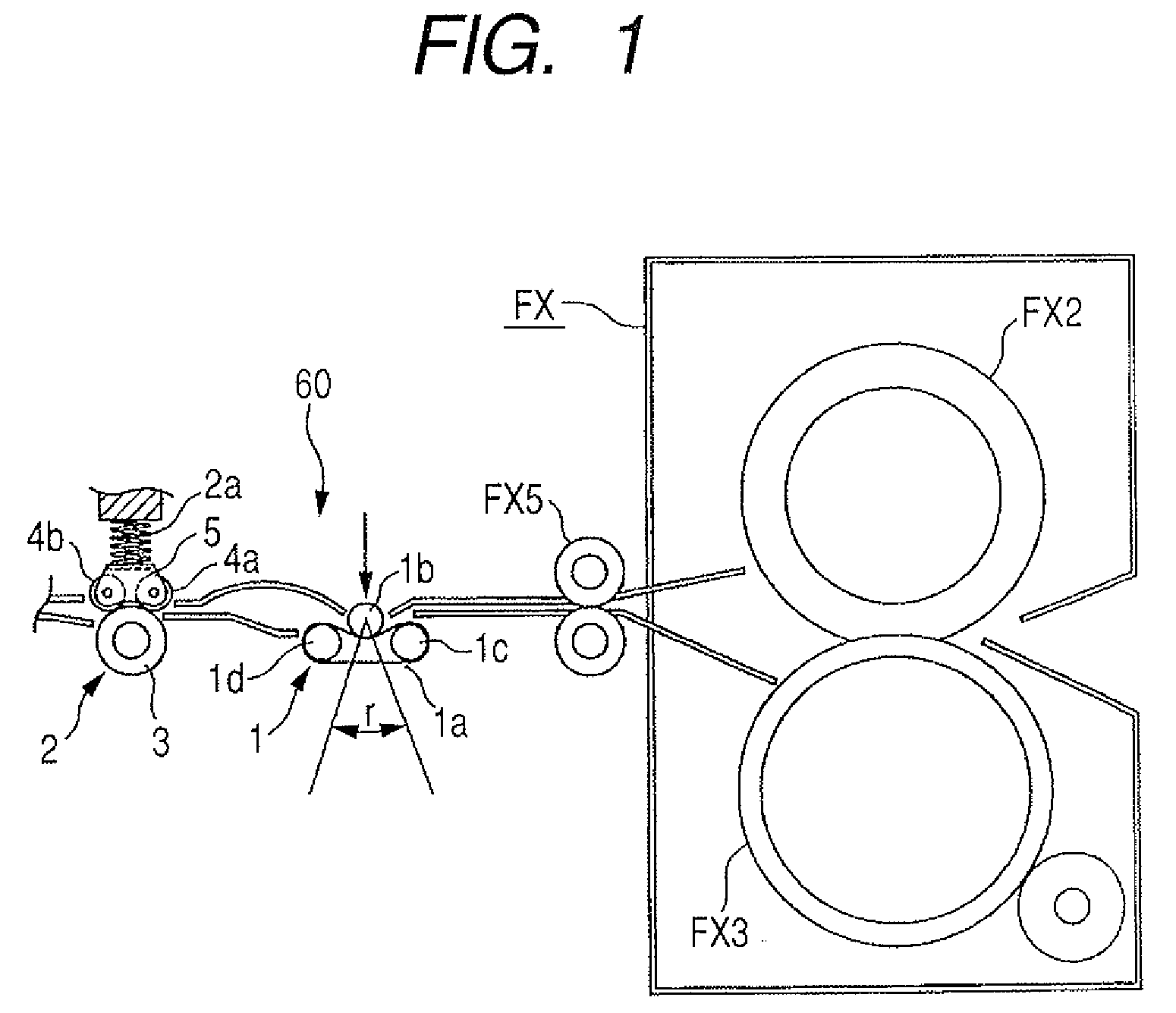
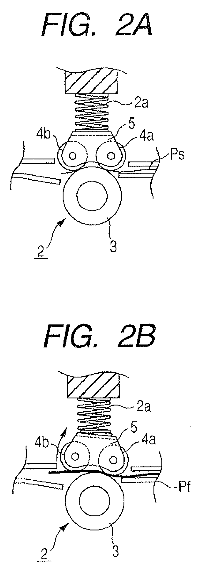
The present invention aims to provide an image forming apparatus that can reliably reform a curved shape of a sheet with a simple structure. The apparatus includes a first curl forming part and a second curl forming part. The second part curls the sheet in a direction opposite to the first part, and the amount of curling in the second part is adjusted based on the rigidity of the sheet. The technical effect of this invention is to improve the quality and efficiency of image formation on sheets, especially those with curved shapes.

Problems solved by technology

In a case of adopting the fixing part employing the heat-pressure fixing system, there arises a problem in that deformation (i.e., curl) is caused on a sheet when the toner image is fixed to the sheet.
For example, in the heat curl generated due to the difference between the amount of water contained in the front surface and that contained in the back surface of the sheet, a large difference in moisture absorption is easily generated between both surfaces of the sheet under such circumstances as thick paper or high humidity, thereby generating a large curl.
When the curled sheet is discharged without reforming the curl, there arises such problems that the sheet is curled up on a discharge tray, or subsequent sheets cannot be stacked on the tray due to blocking of an outlet by the trailing edge of the sheet, thereby deteriorating a stacking property of a sheet.
Here, in a case of the curl reforming apparatus which does not control the curling amount, the pre-curled direction is not fixed to one direction due to the thickness of the sheet or the toner carrying amount as described above, so there is a case where the pre-curled direction matches the curling direction by the curl reforming apparatus, which results in further curling of the sheet.
In such the case, there has been a problem of, for example, curling of the sheet on the discharge tray.
However, in the conventional sheet conveying apparatus, in order to achieve the curl detecting means and the controllable curl reforming means, there has been a problem in that a size of the apparatus is increased and the number of components is increased, which increases the size of the entire image forming apparatus and costs required for the apparatus.

Method used


Image

  • Image forming apparatus
  • Image forming apparatus
  • Image forming apparatus

Examples


first embodiment

[0042]FIG. 3 is a schematic structural view of an image forming apparatus 100 according to the present invention. The image forming apparatus 100 includes an image forming main body 10 (hereinafter, referred to as “main body”) and an image reading part 20 arranged on an upper part of the main body 10.

[0043] The image reading part 20 includes an original feed table 21 on which an original is loaded, a platen roller 22 for conveying the original and positioning a reading position, an original discharge table 23 on which the read original is loaded, and an image sensor 24 for receiving image light to convert the image light into a image signal. In addition, the image recording part 20 includes a first scanning unit 25 and a second scanning unit 26. The first scanning unit 25 is composed of a lamp for illuminating the original and a mirror, and is movable so as to scan the original loaded on an original stacking table 27. The second scanning unit 26 is composed of two mirrors and is mov...

second embodiment

[0073] Next, the present invention will be described.

[0074]FIG. 4 is a structural view of a sheet conveying apparatus provided to an image forming apparatus according to the second embodiment. In FIG. 4, the same reference symbols shown in FIG. 1 denote the identical parts or corresponding parts.

[0075] Reference symbol R3 denotes a straight sheet-discharge path serving as a first conveyance path through which the sheet having passed through the fixing part FX passes. Reference symbol R1 denotes a guide path serving as a second conveyance path which branches from the straight sheet-discharge path R3 and guides the sheet to the reverse conveyance part 14 (see FIG. 4) when the two-side printing mode in which images are formed on both surfaces of the sheet, and the reverse discharge mode are set. Reference symbol R2 denotes a sheet surface reverse path serving as a third conveyance path for conveying the sheet reversed after the sheet passes through the guide path R1 to the straight sh...


PUM


Abstract

The sheet conveying apparatus includes a first curl forming part provided downstream of a fixing part for fixing a toner image to a sheet, for curling the sheet; a second curl forming part provided downstream of the first curl forming part, for curling the sheet in a direction opposite to a direction in which the sheet is curled in the first curl forming part, in which a curling amount of the sheet in the second curl forming part is set to be smaller than that in the first curl forming part, and the curling amount of the sheet in the second curl forming part is variable according to rigidity of the sheet. Thus, a shape of the curled sheet can be reliably reformed with a simple structure.

Description

BACKGROUND OF THE INVENTION [0001] 1. Field of the Invention [0002] The present invention relates to an image forming apparatus, and more particularly, to a sheet conveying apparatus and an image forming apparatus with a structure for reforming a curl generated on a sheet. [0003] 2. Description of the Related Art [0004] Up to now, in an image forming apparatus such as a copying machine and a printer for forming an image by an electrophotographic process, a toner image which has been formed in an image forming part is transferred onto a sheet fed from a sheet feeding part, and the toner image having been transferred onto the sheet is fixed to the sheet in a fixing part. [0005] As an example of such the fixing part, there is a fixing part employing a heat-pressure fixing system for fixing a toner image to a sheet by applying heat and pressure to the sheet at the same time by a rotary member such as a pair of rollers. In a case of adopting the fixing part employing the heat-pressure fi...

Claims


Application Information

Patent Timeline
Patent Type & Authority Applications(United States)
IPC IPC(8): G03G15/00
CPCG03G15/234G03G15/6573G03G2215/00704B65H29/242
Inventor TATEISHI, SATOHISA
Owner CANON KK
Learn More