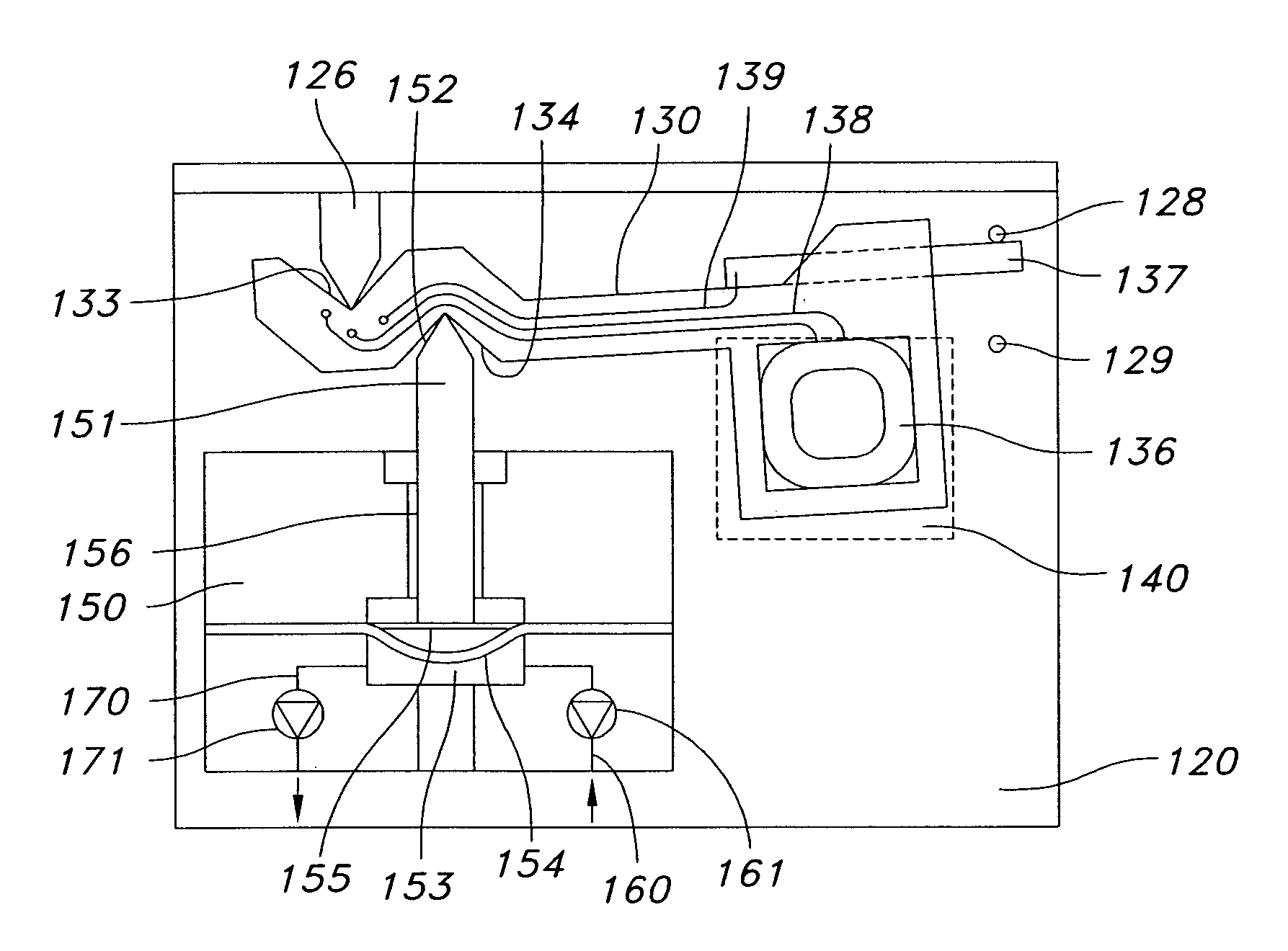
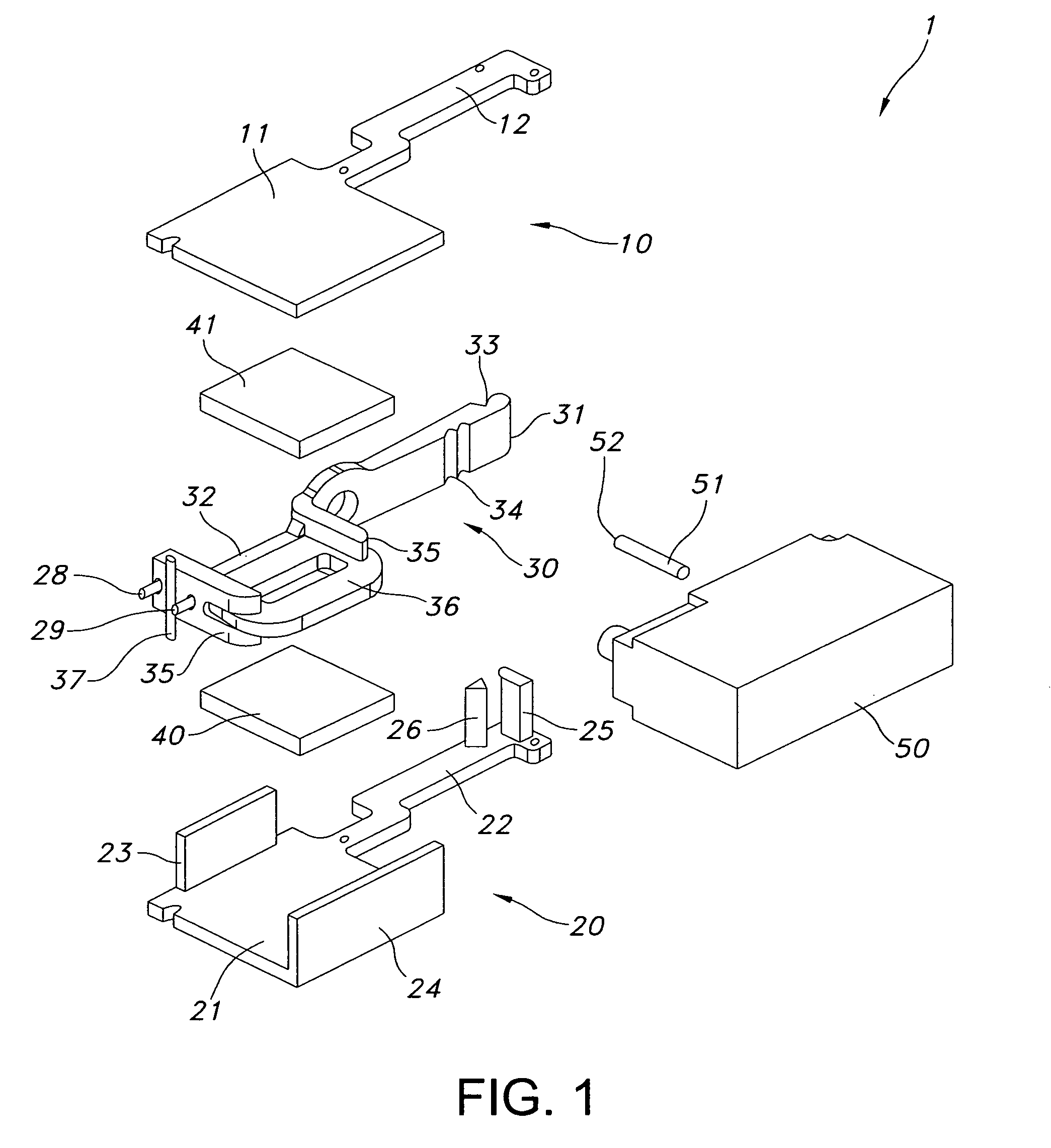
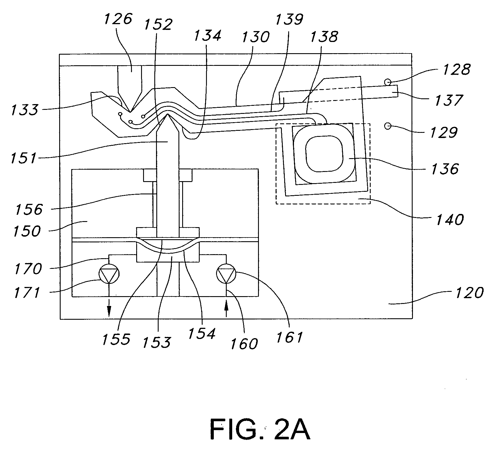
Actuator system comprising lever mechanism
a technology of lever mechanism and actuator, which is applied in the direction of positive displacement liquid engine, process and machine control, instruments, etc., can solve the problems of increasing the pressure inside the pumping chamber, the initial cost of such a pump, and the opening of the outlet valv
- Summary
- Abstract
- Description
- Claims
- Application Information
AI Technical Summary
Benefits of technology
Problems solved by technology
Method used
Image
Examples
example 1
Sticking Valves
[0105] In order to get very tight valves the surfaces of the valve seats as well as the rubber membranes are polished. This leads to sticking between the valve seat and the membrane. This phenomenon was reflected on the pump stroke duration measurements as shown in FIG. 18. At data points #1-15 a freshly assembled, dry pump is pumping air. The valves are sticking which is why the stroke durations are relatively high. At data point #16 the inlet valve gets wet which eliminates the sticking and a fall in inlet stroke duration is seen. A few strokes later the liquid reaches the outlet valve with a similar effect on outlet stroke duration.
example 2
Priming Detection
[0106]FIG. 19 shows the duration of a series of output strokes and a series of input strokes. Data #1-5 shows filling of the conduit connecting the pump to a transcutaneous access device in the form of a hollow hypodermic needle. Output strokes are faster than input strokes because the output stroke is driven by an actuator delivering a high force compared to the input stroke which is driven by the elastic force of the pump membrane itself. At data point #5, the liquid reaches the needle (ID 0.15 mm, 40 mm long) which represents a significantly higher fluid resistance than the connecting channel (ID 0.50 mm) between the pump and the needle. At this point a significant rise in output stroke duration (T-out) is observed. No change is observed at the input stroke duration (T-in). At data point #7 the needle is completely filled, which is why the output stroke duration stabilizes at a new level. This shift in output stroke duration can be used to determine when the pum...
example 3
Occlusion Detection
[0107]FIG. 20 shows what happens if the inlet or the outlet from the pump is occluded. Data points #7-11 show the duration of outlet stroke and inlet stroke when the needle of example 2 is filled with liquid and neither inlet nor outlet is blocked. At data point #11 the outlet is blocked. At the following pump stroke the actuator does not reach its bottom stop position, or does it with a considerable delay. This signal can be used for a very fast and early detection of outlet occlusion. At data point #14 the blocking of the outlet is removed. At data point #16 the inlet is blocked. At the following pump stroke the actuator does not reach its top stop position. This signal can be used for detection of occlusions on the pump inlet. The latter can also be used to detect that a flexible reservoir is close to empty, however, in such a case the rise in T-in will be less dramatic with only a slow rise, but may still be sufficient to detect a close-to-empty reservoir con...
PUM
 Abstract
Description
Claims
Application Information
 - R&D
- Intellectual Property
- Life Sciences
- Materials
- Tech Scout
- Unparalleled Data Quality
- Higher Quality Content
- 60% Fewer Hallucinations
Browse by: Latest US Patents, China's latest patents, Technical Efficacy Thesaurus, Application Domain, Technology Topic, Popular Technical Reports.
© 2025 PatSnap. All rights reserved.Legal|Privacy policy|Modern Slavery Act Transparency Statement|Sitemap|About US| Contact US: help@patsnap.com


