
Network panoramic camera system

a camera system and network technology, applied in the field of network information recording systems, can solve the problems of discontinuities in images, detracting from the overall visual effect, and difficult generation of true 360 degree panoramic images

Inactive Publication Date: 2007-05-10
POLAR INDS
View PDF3 Cites 102 Cited by
  • Summary
  • Abstract
  • Description
  • Claims
  • Application Information

AI Technical Summary

Benefits of technology

[0016] In another alternative, the control subsystem generates processed digital data by digitizing, packetizing and streaming the panoramic imagin...

Problems solved by technology

However, true 360 degree panoramic (“full panoramic”) images are not easy to generate.
Connecting the shots together can often result in discontinuities in the image that detract from the overall visual effect.
However, it is difficult to steadily rotate the image sensor without introducing jitter or other distortion effects.
In addition, the rotation is not performed instantaneously, but rather takes places over time, which can be problematic for live-action or other time sensitive scenes.
However, while these camera modules create RGB images in NTSC and PAL formats, the outputs are analog and are not designed for network use.

Method used


Image

  • Network panoramic camera system
  • Network panoramic camera system
  • Network panoramic camera system

Examples


Embodiment Construction

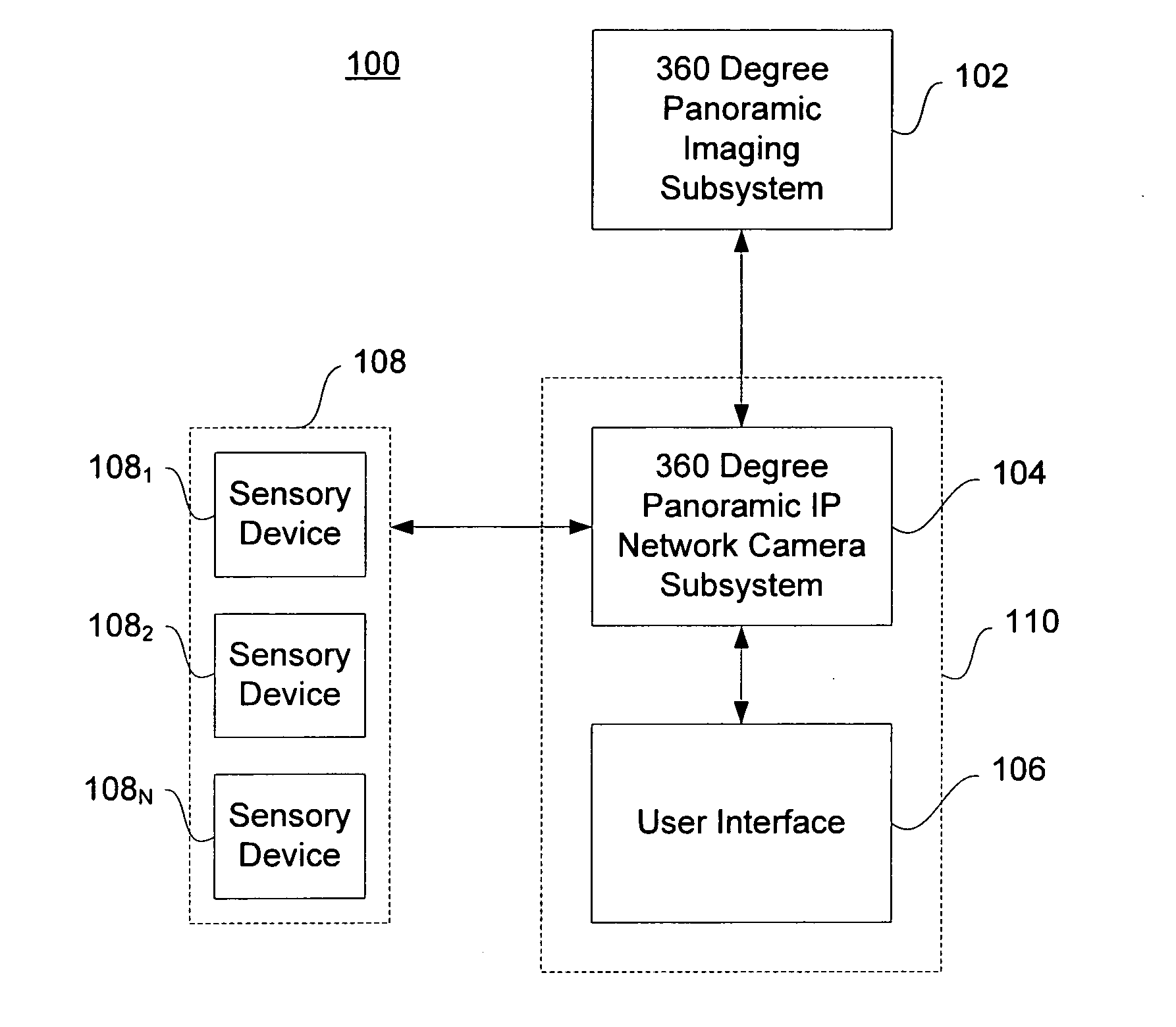
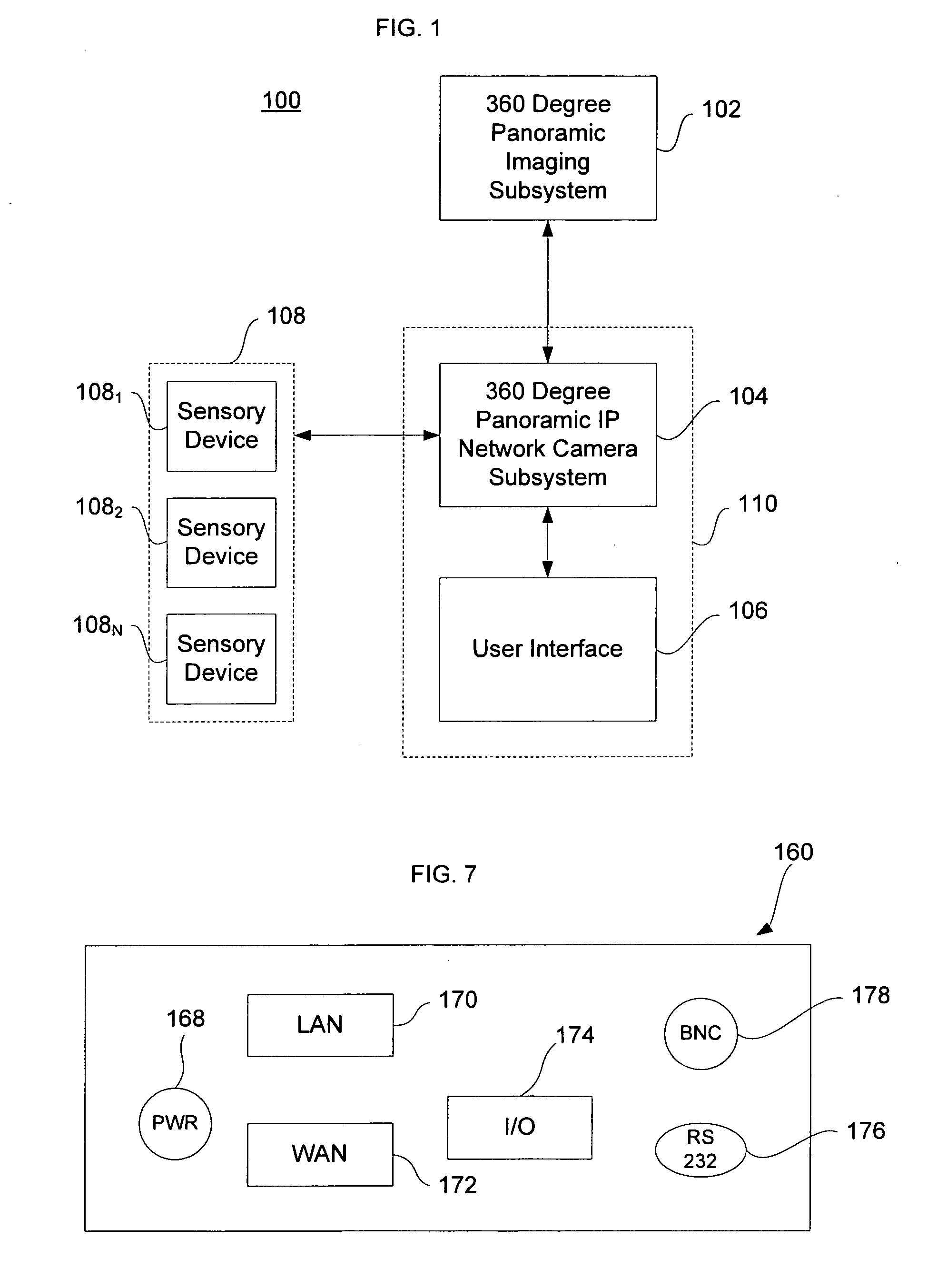
[0039]FIG. 1 illustrates a block diagram of a network panoramic camera system 100 in accordance with a preferred embodiment of the present invention. As shown in this figure, the system 100 includes a 360° imaging subsystem 102, a control subsystem 104 and a user interface 106. One or more sensory devices 108 for sensing environmental conditions may also be connected to the system 100. Desirably, each of these components is capable of generating digital output signals. While only three sensory devices 108 are shown connected in this figure, any number of sensory devices 1081 . . . 108N can be provided. The imaging subsystem 102, the user interface 106, and the sensory devices 108 (if any) are all connected to the control subsystem 104, either directly or indirectly.

[0040] Preferably, the control subsystem 104 and the user interface 106 are incorporated as part of a subsystem 110 to share resources such as a microprocessor, memory and storage. Subsystem 110 can include, for example,...


PUM


Abstract

The present invention provides a 360 degree panoramic IP network camera system. Analog panoramic data is obtained by an imaging subsystem, which is then digitized, processed, encoded, and streamed by a control subsystem in accordance with user input through a graphical user interface. Access to and control of the imaging data may be provided through a web server. The web server enables users across a network to access the imaging data via a web browser-based user interface. Different types and configurations of panoramic images may be generated, processed, stored and displayed for use in a wide variety of application. A video analyzer may also be employed for post processing of data to direct image capture and other information gathering.

Description

CROSS REFERENCE TO RELATED APPLICATION [0001] This application claims the benefit of the filing date of U.S. Provisional Patent Application No. 60 / 706,363 filed Aug. 8, 2005 and entitled “Network Panoramic Camera System,” the entire disclosure of which is hereby incorporated by reference herein.BACKGROUND OF THE INVENTION [0002] The present invention relates generally to network information recording systems. More particularly, the present invention relates to network video recording systems and methods for use with panoramic or wraparound imaging devices. [0003] In the past, imaging devices have been used as an integral part of network-based cameras systems ranging from security applications to videoconferencing to image transfer over the Internet or “webcasting.” Early imaging devices provided low resolution, black and white still image. Over time, the sophistication and capabilities of imaging devices has greatly increased. [0004] For example, while panoramic cameras have been ar...

Claims


Application Information

Patent Timeline
IPC IPC(8): H04N7/00
CPCH04N5/2251H04N5/232H04N5/23206H04N5/23216H04N5/23238H04N5/247H04N7/183H04N23/661H04N23/62H04N23/698H04N23/631H04N23/695H04N23/90
Inventor ANDERSON, GEOFFREY T.PARVULESCU, ADRIAN
Owner POLAR INDS
Learn More