
Apparatus for varying pressure roll nip force

a technology of varying pressure and rolling nip force, applied in the direction of article separation, transportation and packaging, thin material processing, etc., can solve the problems of media advancing some undesirable distance, inconsistent ink droplets, and worsening problems, so as to inhibit media advancing and reducing printing and scanning degradation

Inactive Publication Date: 2007-05-10
LEXMARK INT INC
View PDF24 Cites 22 Cited by
  • Summary
  • Abstract
  • Description
  • Claims
  • Application Information

AI Technical Summary

Benefits of technology

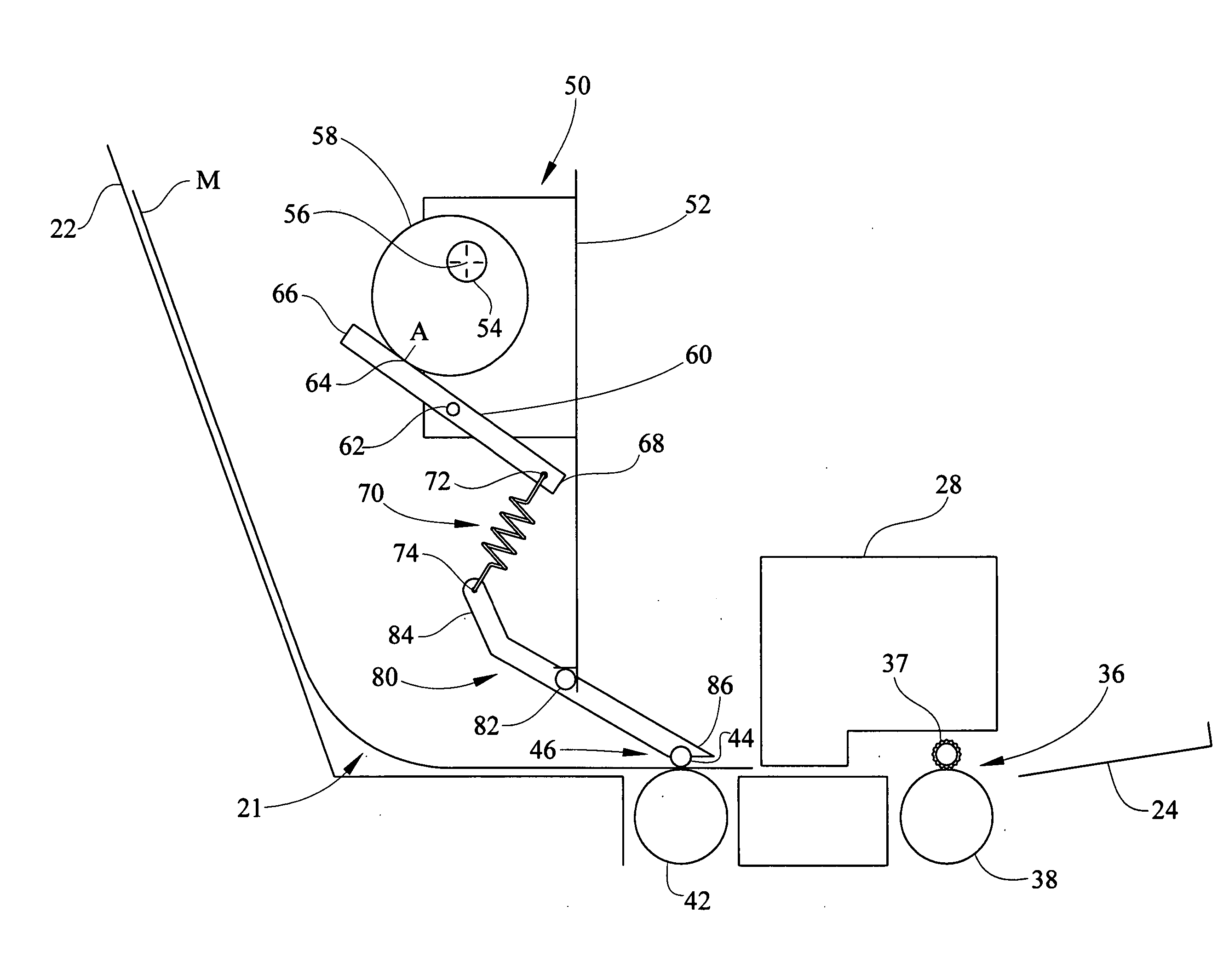
[0014] The present invention inhibits media jump when media exits the nip between the pressure roll and the feed roll.
[0018] According to a fourth embodiment, a variable force pressure roll linkage comprises a media feedpath, a drive roller located along the media feedpath, a biasable idler roller rotatably disposed opposite and biased toward the drive roller and forming a nip therebetween for feeding media, and, a variable force means which decreases biasing force on the idler roller during media exit from the nip.
[0020] The present invention allows for varying of force on a pressure roller when a media trailing edge passes a feed nip thereby inhibiting media jump and printing and scanning degradation.

Problems solved by technology

The media may advance some undesirable distance corresponding to the backlash of a gear train driving the feed roller.
The problem worsens when thicker media is utilized.
Due to the over-advancement of the media, the printhead is moved from its intended position relative to the medium resulting in ink droplets being deposited inconsistently and reduced print quality.
For example, banding may occur which is undesirable.
In the case of ADF scanning, the media jump can result in scanning quality defects.

Method used


Image

  • Apparatus for varying pressure roll nip force
  • Apparatus for varying pressure roll nip force
  • Apparatus for varying pressure roll nip force

Examples


Embodiment Construction

[0031] It is to be understood that the invention is not limited in its application to the details of construction and the arrangement of components set forth in the following description or illustrated in the drawings. The invention is capable of other embodiments and of being practiced or of being carried out in various ways. Also, it is to be understood that the phraseology and terminology used herein is for the purpose of description and should not be regarded as limiting. The use of “including,”“comprising,” or “having” and variations thereof herein is meant to encompass the items listed thereafter and equivalents thereof as well as additional items. Unless limited otherwise, the terms “connected,”“coupled,” and “mounted,” and variations thereof herein are used broadly and encompass direct and indirect connections, couplings, and mountings. In addition, the terms “connected” and “coupled” and variations thereof are not restricted to physical or mechanical connections or coupling...


PUM


Abstract

An apparatus for varying nip pressure in a media feedpath including a feed roller and a pressure roller defining a feed nip there between includes a rotatable cam having a preselected eccentric path when rotated, a first pivotable linkage pivotally engaging the rotatable cam, a second pivotable linkage, a biasing member operably interconnecting the first and second pivotal linkages for providing a biasing force on the pressure roller. The pressure roller is rotatably connected to the second linkage opposite the biasing member, wherein rotation of the cam varies the biasing force provided by the biasing member on the pressure roller.

Description

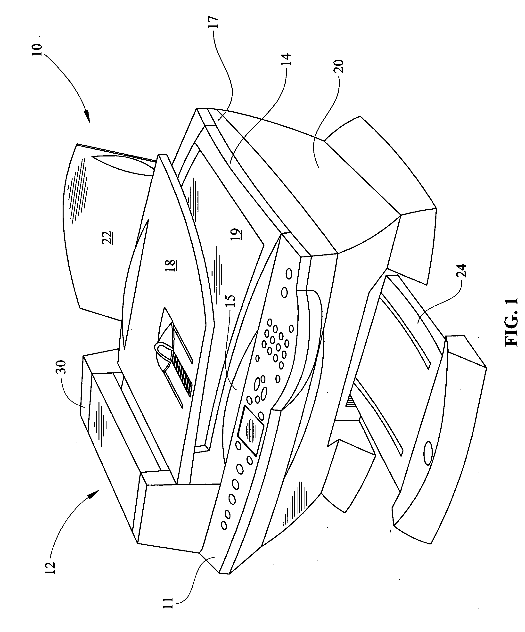
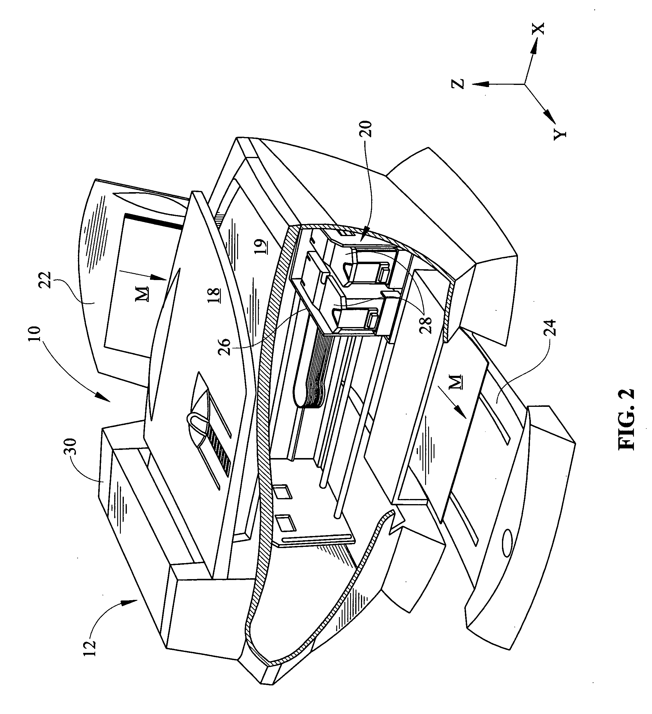
CROSS REFERENCES TO RELATED APPLICATIONS [0001] None. STATEMENT REGARDING FEDERALLY SPONSORED RESEARCH OR DEVELOPMENT [0002] None. REFERENCE TO SEQUENTIAL LISTING, ETC. [0003] None. BACKGROUND [0004] 1. Field of the Invention [0005] The present invention relates generally to media feed mechanisms, and more particularly to a media feed mechanisms in printing and / or scanning mechanisms. [0006] 2. Description of the Related Art [0007] All-in-one machines typically perform functions such as printing, scanning, copying, and faxing in either a stand alone fashion or in conjunction with a personal computer and define a growing market for peripheral devices. These devices eliminate clutter in a business or home office by combining the desirable functionality of various machines into a single unit, while maintaining an affordable cost. Various all-in-one machines currently in the marketplace use thermal inkjet technology as a means for printing received fax documents, original documents, and...

Claims


Application Information

Patent Timeline
Patent Type & Authority Applications(United States)
IPC IPC(8): B65H5/02B65H5/04
CPCB65H5/062B65H2511/224
Inventor ACTON, LARRY W.CONNORS, WILLIAM M.GAGNON, DANIEL R.SMITH, HERMAN A.
Owner LEXMARK INT INC
Learn More