
Separating device, holding device and method for separation

a technology of holding device and separation device, which is applied in the direction of gravity filter, loose filtering material filter, cartridge filter, etc., can solve the problems of inability to access the interior, inability to ensure the reliability of the separation medium through the perforation located in the separation device, and inability to prevent the satisfaction of the separation in all cases. , to achieve the effect of high degree of purity, simple design and reliable operation

Inactive Publication Date: 2007-05-10
GREINER BIO ONE GMBH
View PDF31 Cites 72 Cited by
  • Summary
  • Abstract
  • Description
  • Claims
  • Application Information

AI Technical Summary

Benefits of technology

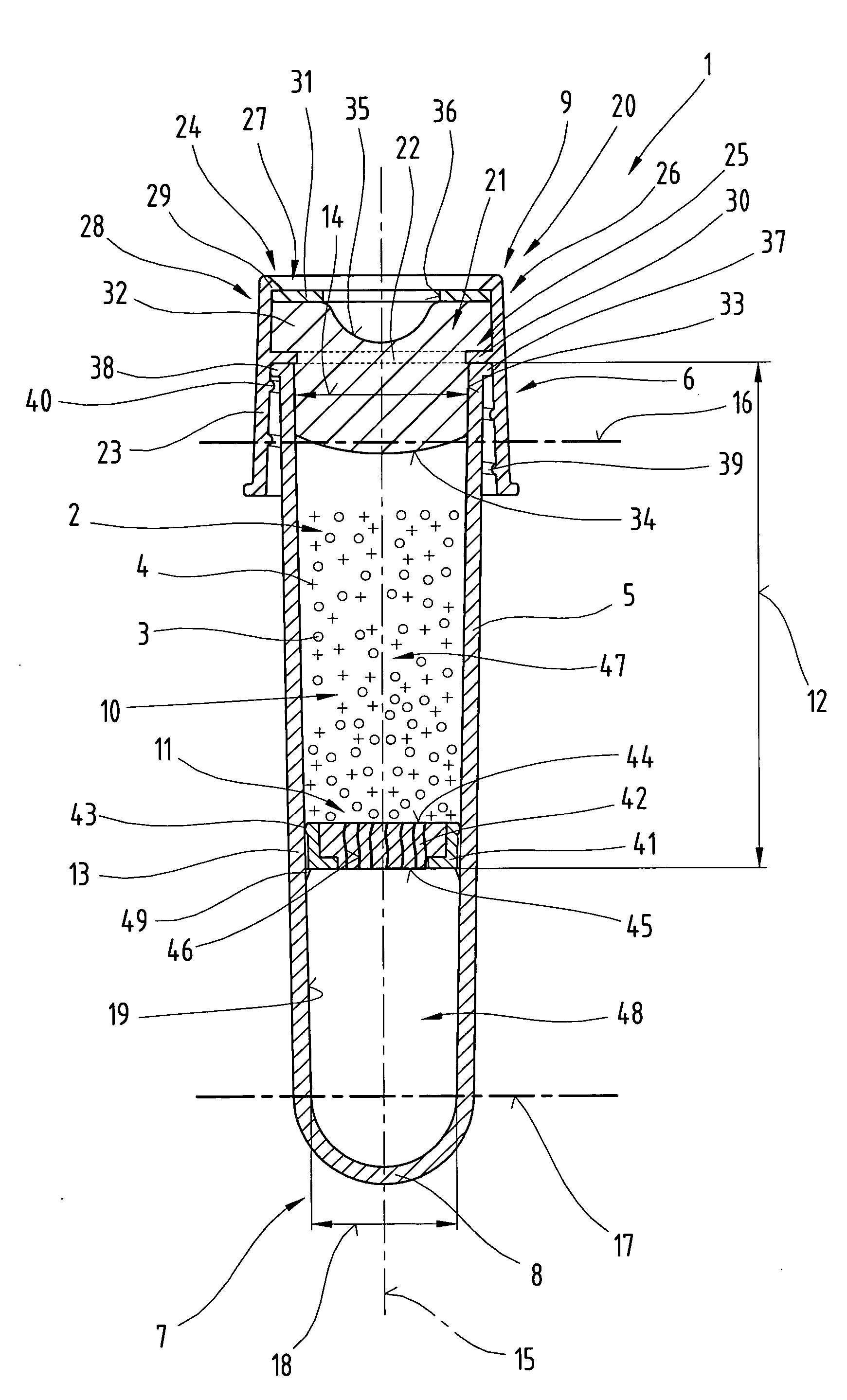
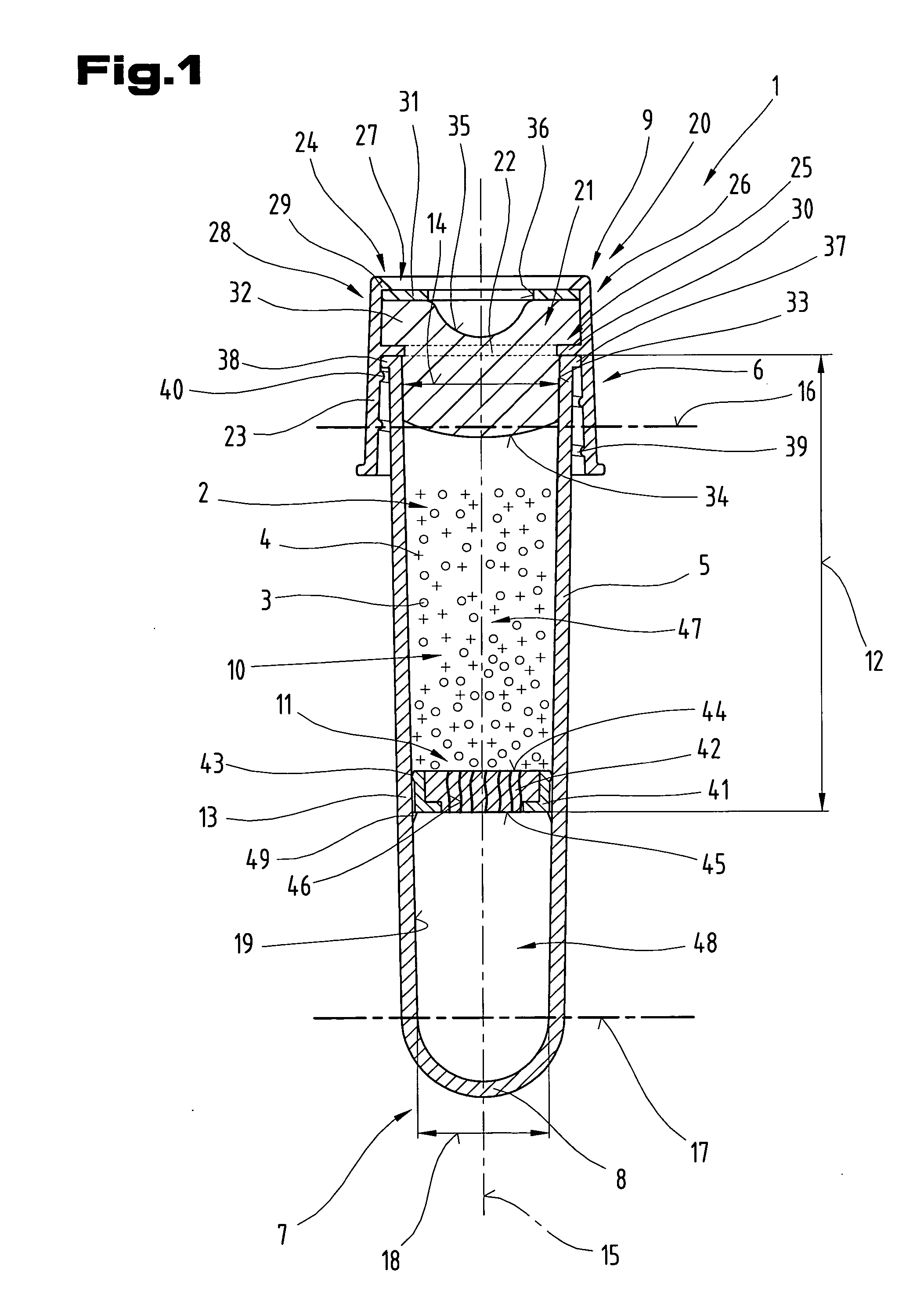
"The invention is a separation device for use in a holding container for a holding device. The device is designed to separate components of a substance such as blood, tissue parts, and tissue cultures. The device includes a movable plunger that can deform under the influence of centrifugal force and is designed to allow the lighter components to pass through while keeping the heavier components in place. The device can be used in blood test tubes and is important for accurate separation of blood components for medical analysis. The invention provides an improved method for separating components of a substance, especially for use in blood testing."

Problems solved by technology

Satisfactory separation could not be prevented in all cases.
The joining of the individual components, in particular the insertion of the separation device, is performed in a vacuum chamber because after inserting the separation device, access to the interior is no longer possible without damaging the separation device.
One disadvantage of this variant is that a special tube with a stop on the inside must be manufactured, and reliable medium separation through the perforation situated in the separation device cannot be ensured.
In addition, a permanent tight seal between the two separate phases is not always possible.
The disadvantage here is that in many cases the duration of storage is not sufficient for a normal use time due to the fact that the separation device is made of a gel.

Method used


Image

  • Separating device, holding device and method for separation
  • Separating device, holding device and method for separation
  • Separating device, holding device and method for separation

Examples


Embodiment Construction

[0056] By way of introduction, it should be pointed out that the same parts in the different embodiments described here are labeled with the same reference numerals and / or the same component designations, whereby the disclosure contained in the entire description can be applied appropriately to the same parts with the same reference numerals and / or the same component designations. The position information (e.g., above, below, at the side, etc.) selected in the description is based on the figure being presented and described directly and can be scaled up appropriately to the new position when there is a change in position. In addition, individual features or combinations of features from the various exemplary embodiments illustrated and described here may constitute independent or inventive embodiments or may be used according to the invention.

[0057] The exemplary embodiments show possible design variants of the separation device and / or a holding device, and it should be pointed out...


PUM

PropertyMeasurementUnit
sizeaaaaaaaaaa
diameteraaaaaaaaaa
diameteraaaaaaaaaa

Abstract

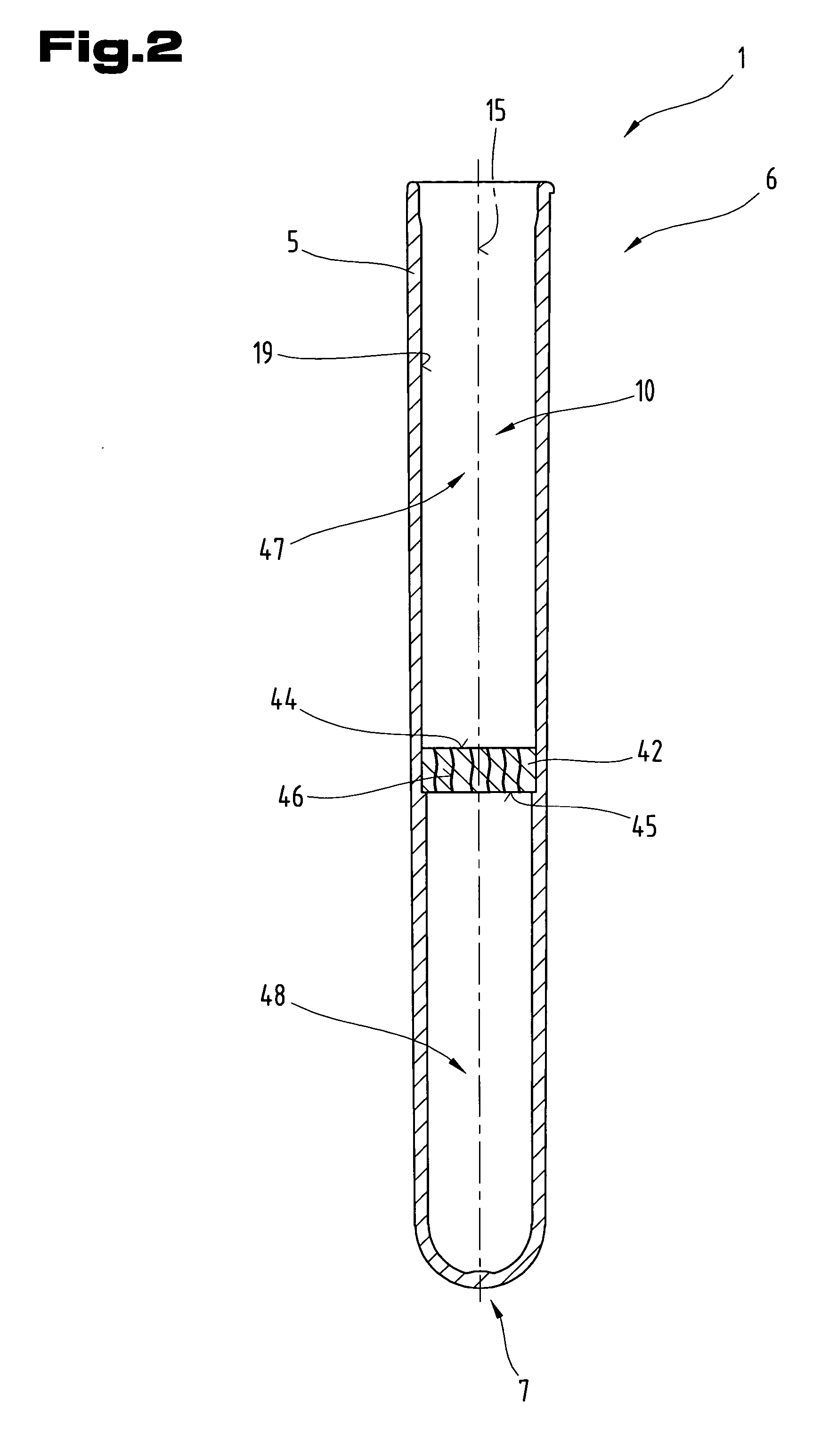
The invention describes a separation device (11) for insertion into an interior space (10) of a holding container (5) of a holding device (1) for the components of substances to be separated such as body fluids, tissue parts and / or tissue cultures, whereby the separation device (11) comprises at least one separation element (42) with end faces (44, 45) set a distance apart from one another in the direction of the longitudinal axis (15) and several channels (56) extending between the two end faces (44, 45) are arranged in the separation element (42). The channels (46) arranged in the separation element (42) are designed so that in a working position they allow the components of the substance to be separated to pass through exclusively while a compressive force is being applied to the substance, and in a separation position, the channels (46) suppress the passage of the components that are to be separated. In addition the invention also relates to a holding device (1) equipped with this separation device (11) and a method for separation of components to be separated.

Description

BACKGROUND OF THE INVENTION [0001] 1. Field of the Invention [0002] The invention relates to a separation device for use in the interior space of a holding container, a holding device equipped therewith and a method for separating components of a substance such as a body fluid, tissue parts and / or tissue cultures, as described in claims 1, 28 and 52. [0003] 2. Prior Art [0004] Various methods and equipment for treatment are already known. Substances such as blood are divided into a light phase and a heavy phase. The light phase in the case of blood is formed by blood serum and / or blood plasma, for example, whereas the heavy portion of blood is formed by cellular components such as blood cells. [0005] The plunger movable in the interior space of the blood test tube under the influence of centrifugal force, especially in centrifugation of the sample, is usually designed so that it is deformed under the influence of centrifugal force and permits passage of the lightweight components up...

Claims


Application Information

Patent Timeline
Patent Type & Authority Applications(United States)
IPC IPC(8): B01D35/00
CPCB01L3/50215B01L2200/12B01L2300/044B01L2300/0681B01L2400/0409B01L2400/06
Inventor KONRAD, FRANZ
Owner GREINER BIO ONE GMBH
Learn More