
High frequency oscillator ventilator

a high frequency oscillator and ventilator technology, which is applied in the field of medical equipment, can solve the problems of affecting the overall utility of the hfov, the inability of the patient's lungs to provide adequate ventilation or gas exchange, and the prior art's several deficiencies that detract from the overall utility, so as to reduce the noise produced by the hfov of the present invention, eliminate the slapping sound, and reduce the power consumption of the hfo

Active Publication Date: 2007-05-10
VYAIRE MEDICAL 211 INC
View PDF20 Cites 45 Cited by
  • Summary
  • Abstract
  • Description
  • Claims
  • Application Information

AI Technical Summary

Benefits of technology

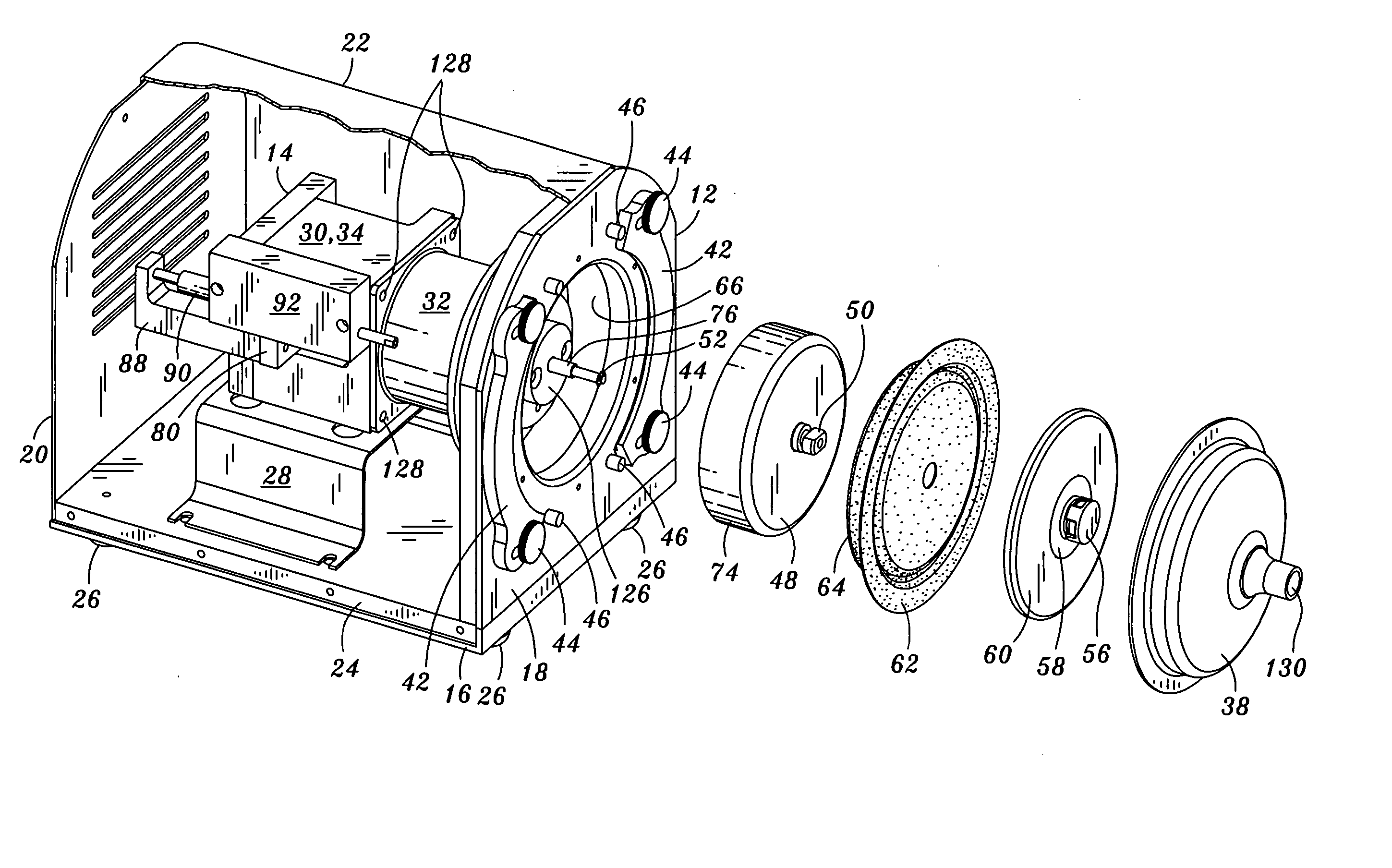
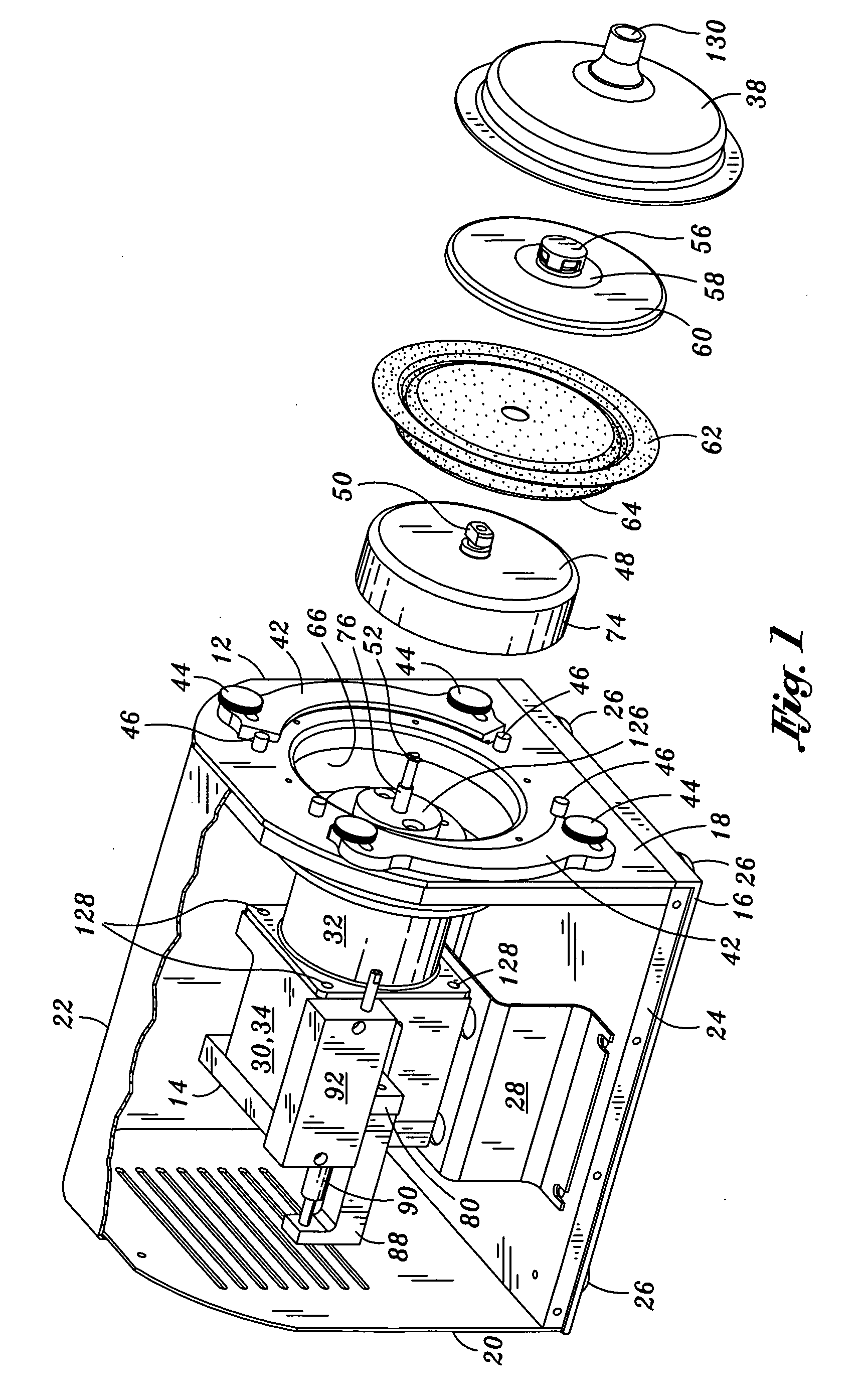
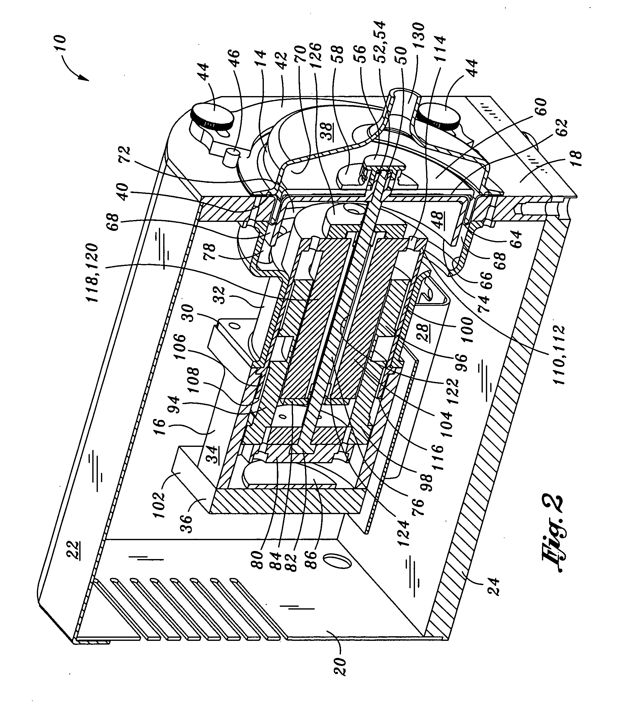
[0013] The present invention specifically addresses and alleviates of the above-referenced deficiencies associated with high frequency oscillating ventilators (HFOV's) of the prior art. More particularly, the present invention is an improved HFOV that is configured to match the clinical performance of existing HFOV's but at a reduced size and with reduced noise and power consumption through the use of a pushrod-suspended linear coil as well as the incorporation of a rolling diaphragm in the HFOV and which is directly engaged to a piston.
[0015] Replaceability of the diaphragm is facilitated through the use of a cone cover which is secured to a housing assembly of the HFOV by a pair of hold down brackets. A pair of thumbscrews secured into the housing assembly through opposing ends of the hold down brackets allow for quick release and removal of the cone cover for access to the diaphragm. An opening formed in the cone cover fluidly communicates with the patient's airway for delivering gas thereto. The gas is supplied by a source of gas such as compressed gas or oxygen.
[0017] Noise produced by the HFOV of the present invention is greatly reduced compared to conventional HFOV's due to the incorporation of a deep radius groove formed about a periphery of the diaphragm such that the diaphragm is essentially non-inverting. The specific configuration of the diaphragm of the present invention eliminates a popping sound that occurs during rapid frequency oscillations of the piston and diaphragm in prior art HFOV's. Furthermore, the diaphragm of the present invention is directly affixed or attached to the piston as opposed to an intermittent engagement that occurs therebetween during the forward stroke of the piston of prior art HFOV's. Such direct attachment of the piston to the diaphragm eliminates the slapping sound that is generated by prior art HFOV's when the piston repetitively strikes the underside of the diaphragm during the piston's forward stroke.
[0018] As was earlier mentioned, power consumption of the HFOV of the present invention is also reduced as compared to prior art HFOV's due to the use of a pushrod extending through the linear actuator which results in an essentially free-floating linear coil. As compared to prior art HFOV's which use radially-extending spider springs for centering and maintaining the position of the linear coil and piston, power consumption in the HFOV of the present invention is greatly reduced due to the lack of spring forces.
[0019] Advantageously, the centering of the piston in the present invention is facilitated by a sensor such as an optical sensor which is connected to the pushrod. An inner-loop control system provides a closed-loop feedback mechanism by which the position of the piston is accurately maintained at all times despite variations in temperature in the coil which, as was earlier mentioned, affects the accuracy with which the piston is centered. Cooling of the actuator assembly of the present invention is facilitated through the use of ventilation ports formed in the housing assembly which allow for convective cooling by atmospheric air circulating through the actuator assembly.

Problems solved by technology

In some cases, the lungs of the patient may be incapable of providing adequate ventilation or gas exchange, particularly in the exhalation phase.
Despite their advantages, HFOV's of the prior art suffer from several deficiencies that detract from their overall utility.
Although the HFOV as disclosed in the Jensen reference is effective in producing gas exchange in ventilation of a patient without damaging the patients lungs such by over-pressurization, this HFOV unfortunately produces relatively high noise levels which are undesirable in sensitive environments wherein HFOV's are typically used such as neonatal intensive care units.
Unfortunately, a relatively large amount of power is required to overcome the significant spring forces when reciprocating the linear actuator relative to the coil to cause the diaphragm to vibrate.
In this regard, a further deficiency associated with this HFOV is excess heating of the coil which degrades the accuracy with which the piston is centered due to resistance changes in the coil as the coil heats up.
High noise levels produced by prior art HFOV's noise may be generated by several sources including noise produced by the fan as well as noise produced by the flow of cooling air traveling through various passageways formed in the coil.
Because such cooling gas exit the coil and enter the surrounding environment, additional noise is produced by the out rush of cooling gas through apertures in the coil housing.
A further significant source of noise that may be disruptive to patients as well as to hospital personnel is noise that is generated by the diaphragm.
Unfortunately, the consistent back and forth motion of the diaphragm causes the relief to constantly invert in rapid succession creating a snapping noise as the reciprocations occur.
A further source of noise is generated by the piston as it contactor strikes an underside the diaphragm in a repetitive manner during each positive stroke.
The constant repetitive striking of the bottom of the diaphragm generates the repetitive slapping noise which only adds to the overall noise produces by the HFOV and which unfortunately disrupts the patient's sleep and recovery.
For example, HFOV's of the type described above may produce noise levels of up to 65 dB when operating at full power.

Method used


Image

  • High frequency oscillator ventilator
  • High frequency oscillator ventilator
  • High frequency oscillator ventilator

Examples


Embodiment Construction

[0025] The present invention will now be described in particular with reference to the accompanying drawings wherein FIGS. 1-3 illustrate a high frequency oscillating ventilator (HFOV) 10 which, in its broadest sense, comprises a housing assembly 30 having an actuator assembly 102 mounted thereupon. The actuator assembly 102 is comprised of a linear actuator 104 and a linear coil 94 having a pushrod 76 which supports the linear coil 94 on the linear actuator 104. The pushrod 76 is axially slideable within the linear actuator 104 and is directly mounted to a diaphragm 62 which sealingly divides the housing assembly 30 into a first side 70 and a second side 72. The actuator assembly 102 is configured to effectuate reciprocation of the piston 48 and diaphragm 62 in a manner to alternately produce positive and negative pressure waves in gas provided to a patient's airway.

[0026] The actuator assembly 102 may be configured as a linear motor which is similar to the type shown and describe...


PUM


Abstract

Provided is a high frequency oscillating ventilator comprising a housing assembly, a linear actuator, a linear coil, a piston mounted on a pushrod, a diaphragm dividing a housing into a first and second side and having an opening formed on the second side that is fluidly connected to the patient's airway for delivering gas thereto. The linear actuator is fixedly mounted to the housing assembly and has a linear coil coaxially disposed therewithin. A pushrod supports the linear coil on the linear actuator to allow relative axially sliding therebetween. The piston is directly mounted to the diaphragm such that reciprocation thereof as effectuated by the linear coil cooperating with the linear actuator alternately produces positive and negative pressure waves in the gas in the patient's airway.

Description

CROSS-REFERENCE TO RELATED APPLICATIONS [0001] (Not Applicable) STATEMENT RE: FEDERALLY SPONSORED RESEARCH / DEVELOPMENT [0002] (Not Applicable) BACKGROUND OF THE INVENTION [0003] The present invention relates generally to medical equipment and, more particularly, to a high frequency oscillating ventilator for producing positive and negative pressure waves in respiratory air that is supplied to a patient. Advantageously, the high frequency oscillating ventilator (HFOV) of the present invention is specifically configured to operate at reduced noise levels and under reduced power as compared to HFOV's of the prior art. [0004] As opposed to conventional ventilators which ventilate only during the inhalation phase and which rely on human physiological response for ventilation during the expiration phase, HFOV's produce an active exhalation which is critical in the respiration of certain types of patients such as in neonates and / or other child or adult patients suffering from certain lung ...

Claims


Application Information

Patent Timeline
Patent Type & Authority Applications(United States)
IPC IPC(8): A62B9/06A61M16/00
CPCA61M16/0096A61M2205/0288F04B45/041F04B45/047F04B45/10A61M16/0057A61M16/04A61M16/0875A61M16/208A61M2016/0027A61M2205/42A61M16/0009F04B49/06
Inventor DUQUETTE, STEVENWESTFALL, THOMASHAN, STEVE
Owner VYAIRE MEDICAL 211 INC
Learn More