
Compact lancing apparatus

a lancing device and compact technology, applied in the field of lancing devices, can solve the problems of multiple lancing, unintentional multiple lancing, and the inability of the lancing device to penetrate the target site,

Inactive Publication Date: 2007-05-03
LIFESCAN SCOTLAND
View PDF20 Cites 87 Cited by
  • Summary
  • Abstract
  • Description
  • Claims
  • Application Information

AI Technical Summary

Problems solved by technology

The lancing of a dermal tissue target site by a conventional lancing device can be unduly painful for several reasons.
First, post-launching recoil can cause a lancet to re-penetrate a target site, albeit at a site slightly skewed point with respect to the original lancet penetration point.
Such post-launching recoil can, therefore, result in unintentional multiple lancing and an increase in pain.
Second, conventional lancing devices may rely on the spring constant of a lancing spring to define a lancet's penetration depth.
However, over time the spring constant may change, thus detrimentally altering the penetration depth.
Third, a sudden motion-based impulse emanating from the lancing device housing (i.e., a side-effect of launching) may be noticed by a user.
The anticipation of such impulses may be disconcerting to the user.

Method used


Image

  • Compact lancing apparatus
  • Compact lancing apparatus
  • Compact lancing apparatus

Examples


Embodiment Construction

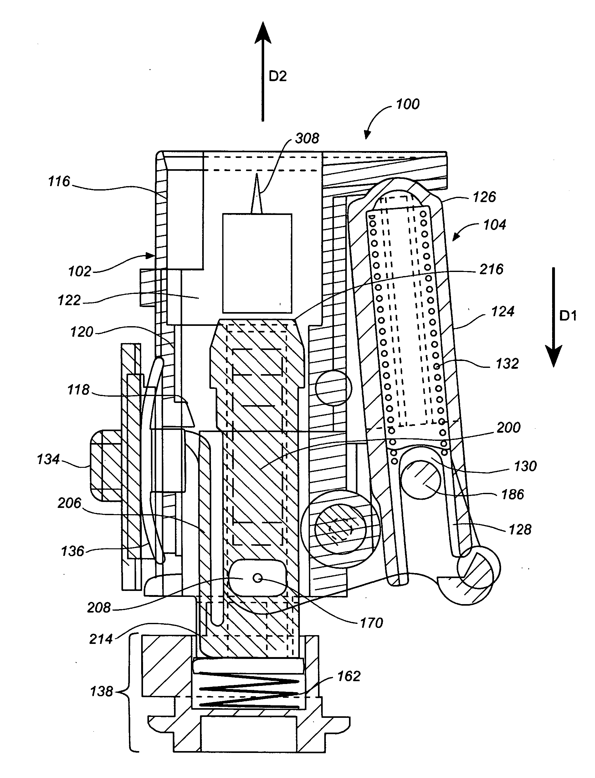
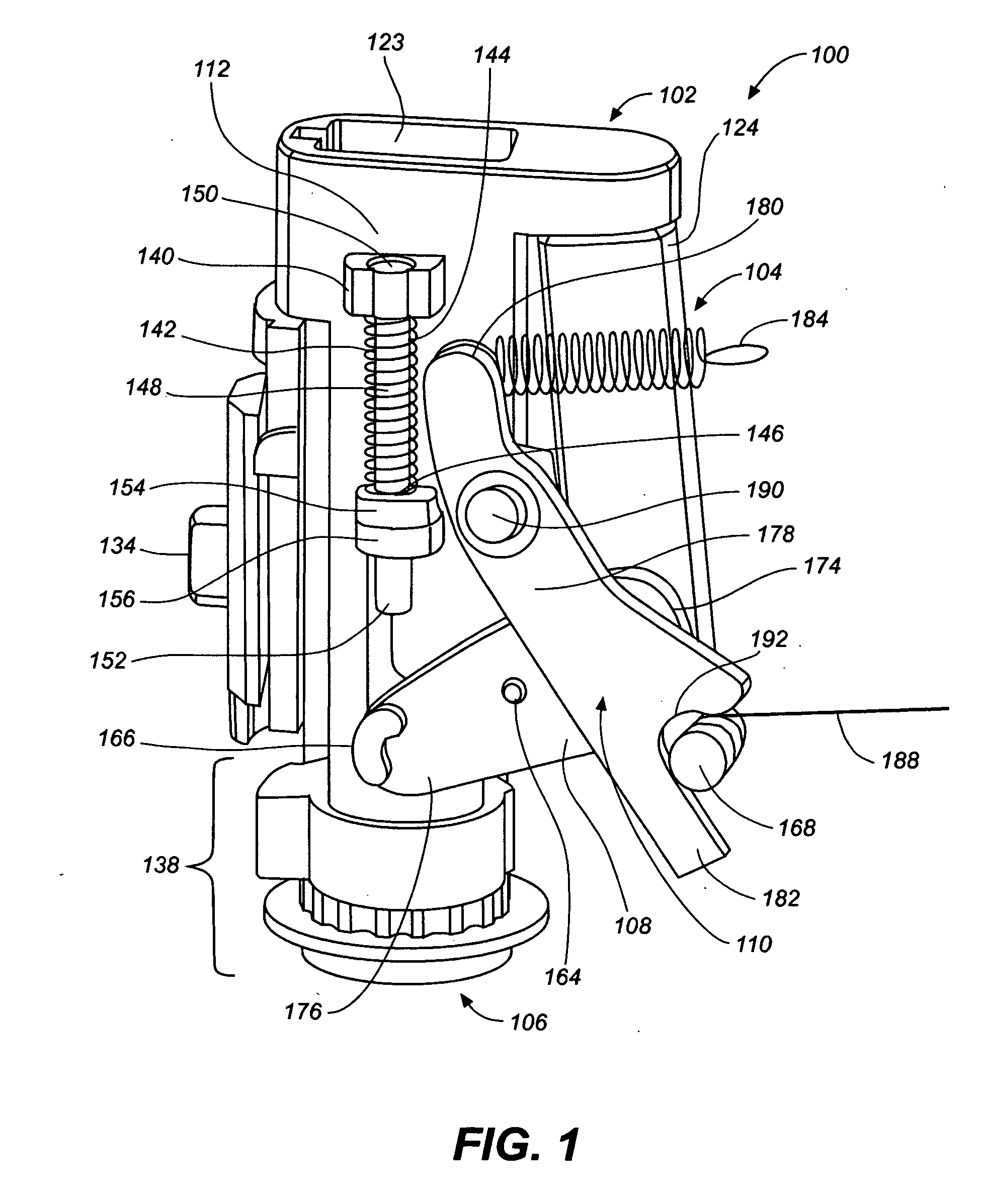
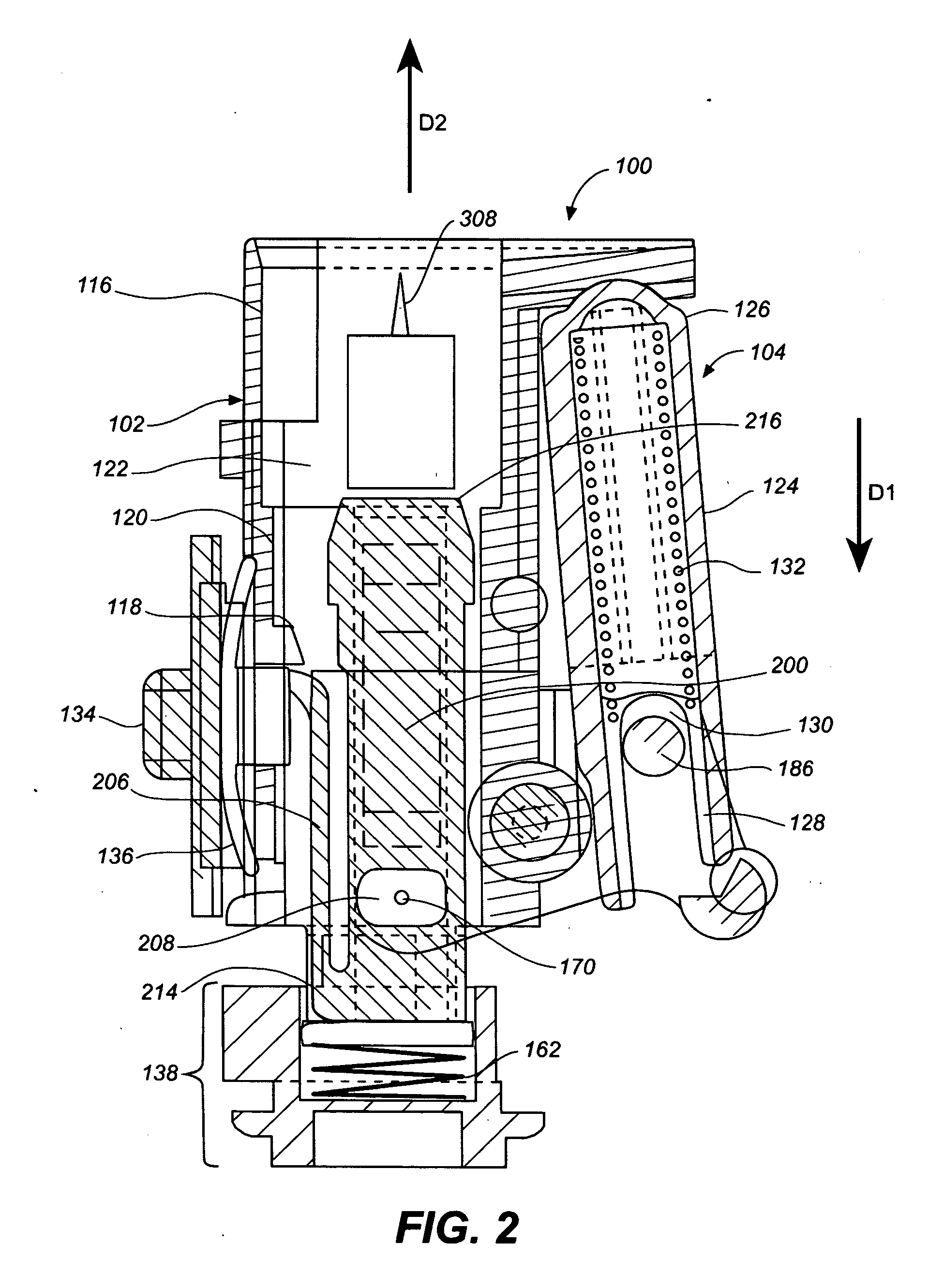
[0022] As is described in more detail below with respect to specific embodiments illustrated in the FIG. 1, lancing apparatuses according to embodiments of the present invention include an inner housing, a firing mechanism, a lancing mechanism and a linkage arm. The firing mechanism is configured for producing a firing force in a first direction. The lancing mechanism is configured for delivering a lancing force in a second direction with the second direction being toward a target site and in opposition to the first direction. The linkage arm is pivotably attached to the housing and has first and second ends engaged to the firing and lancing mechanisms, respectively. During use, pivoting of the linkage arm converts the firing force in the first direction into the lancing force in the opposing second direction.

[0023] Lancing apparatus according to embodiments of the present invention are beneficially compact and relatively simple in construction. In addition, post-launching recoil i...


PUM


Abstract

A lancing apparatus includes an inner housing, a firing mechanism, a lancing mechanism and a linkage arm. The firing mechanism is configured for producing a firing force in a first direction. The lancing mechanism is configured for delivering a lancing force in a second direction with the second direction being toward a target site and in opposition to the first direction. The linkage arm is pivotably attached to the housing and has first and second ends engaged to the firing and lancing mechanisms, respectively. During use, pivoting of the linkage arm converts the firing force in the first direction into the lancing force in the opposing second direction.

Description

BACKGROUND OF THE INVENTION [0001] 1. Field of the Invention [0002] The present invention relates, in general, to medical devices and systems and, in particular, to lancing devices and associated systems. [0003] 2. Description of the Related Art [0004] A variety of medical conditions, such as diabetes, call for the monitoring of an analyte concentration (e.g., glucose concentration) in a blood, interstitial fluid or other bodily fluid sample. Typically, such monitoring requires the extraction of a bodily fluid sample from a target site (e.g., a dermal tissue target site on a user's finger). The extraction (also referred to as “expression”) of a bodily fluid sample from the target site generally involves lancing the dermal tissue target site with a lancing device and then expressing the bodily fluid sample from the lanced site. [0005] Conventional lancing devices typically have a rigid housing and a lancet that can be armed (also referred to as “primed”) and launched (also referred t...

Claims


Application Information

Patent Timeline
Patent Type & Authority Applications(United States)
IPC IPC(8): A61B17/32
CPCA61B5/1411A61B5/14532A61B5/15186A61B2562/0295A61B5/150022A61B5/150259A61B5/150358A61B5/150442A61B5/15113A61B5/15117A61B5/15128A61B5/1519A61B5/15194A61B5/157A61B5/150198
Inventor SANSOM, GORDON GEORGE
Owner LIFESCAN SCOTLAND
Learn More