
Integrateable Optical Interleaver and De-Interleaver

a technology of interleaver and interleaver, which is applied in the direction of optics, optical multiplex, instruments, etc., can solve the problems of poor extinction ratio, high electrical power consumption of switches, and significant loss of mmi couplers

Inactive Publication Date: 2007-05-03
LUCENT TECH INC
View PDF21 Cites 5 Cited by
  • Summary
  • Abstract
  • Description
  • Claims
  • Application Information

AI Technical Summary

Problems solved by technology

This has an accurate power-off state, but often a poor extinction ratio.
“Y” switches consume high electrical power when operated thermo-optically in silica waveguides, and so are limited to only materials like LiNbO3, InP, and polymers.
However, MMI couplers have significant loss, resulting in a 1×2 optical switch with typically 1.2 dB loss in silica waveguides.

Method used


Image

  • Integrateable Optical Interleaver and De-Interleaver
  • Integrateable Optical Interleaver and De-Interleaver
  • Integrateable Optical Interleaver and De-Interleaver

Examples


Embodiment Construction

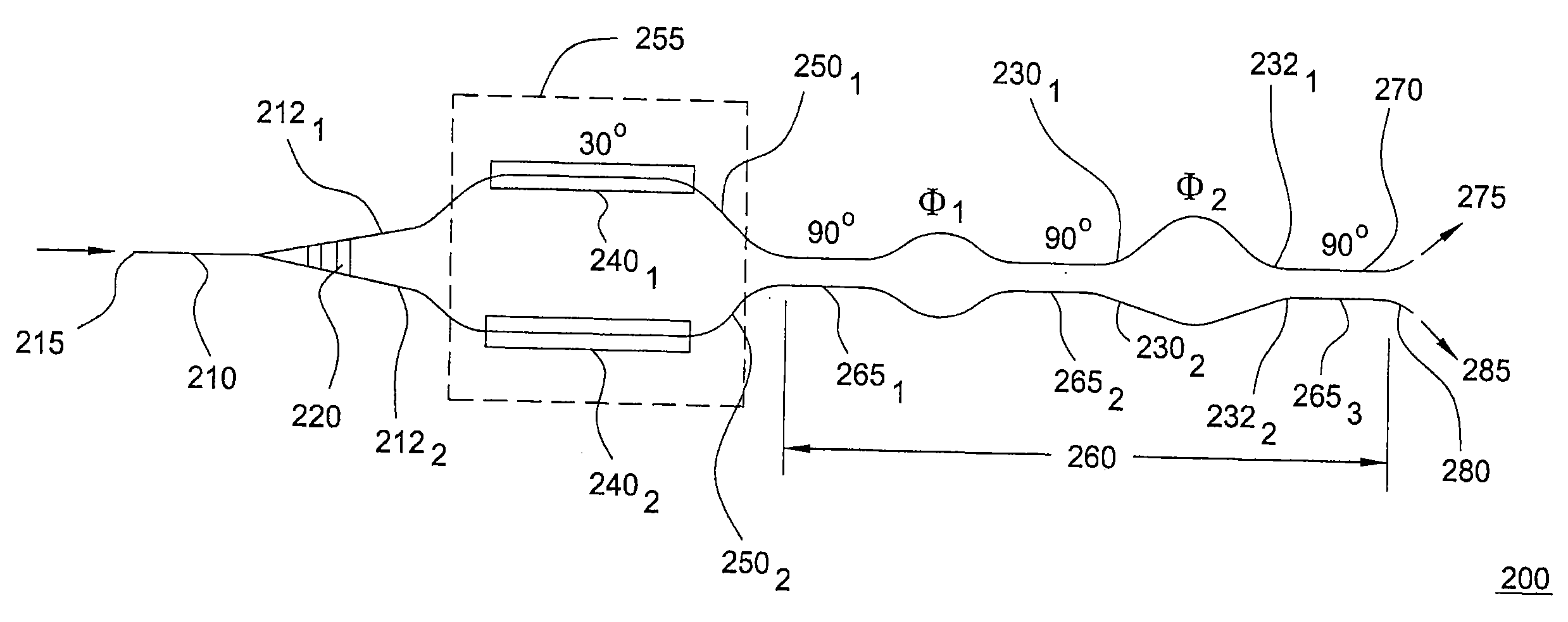
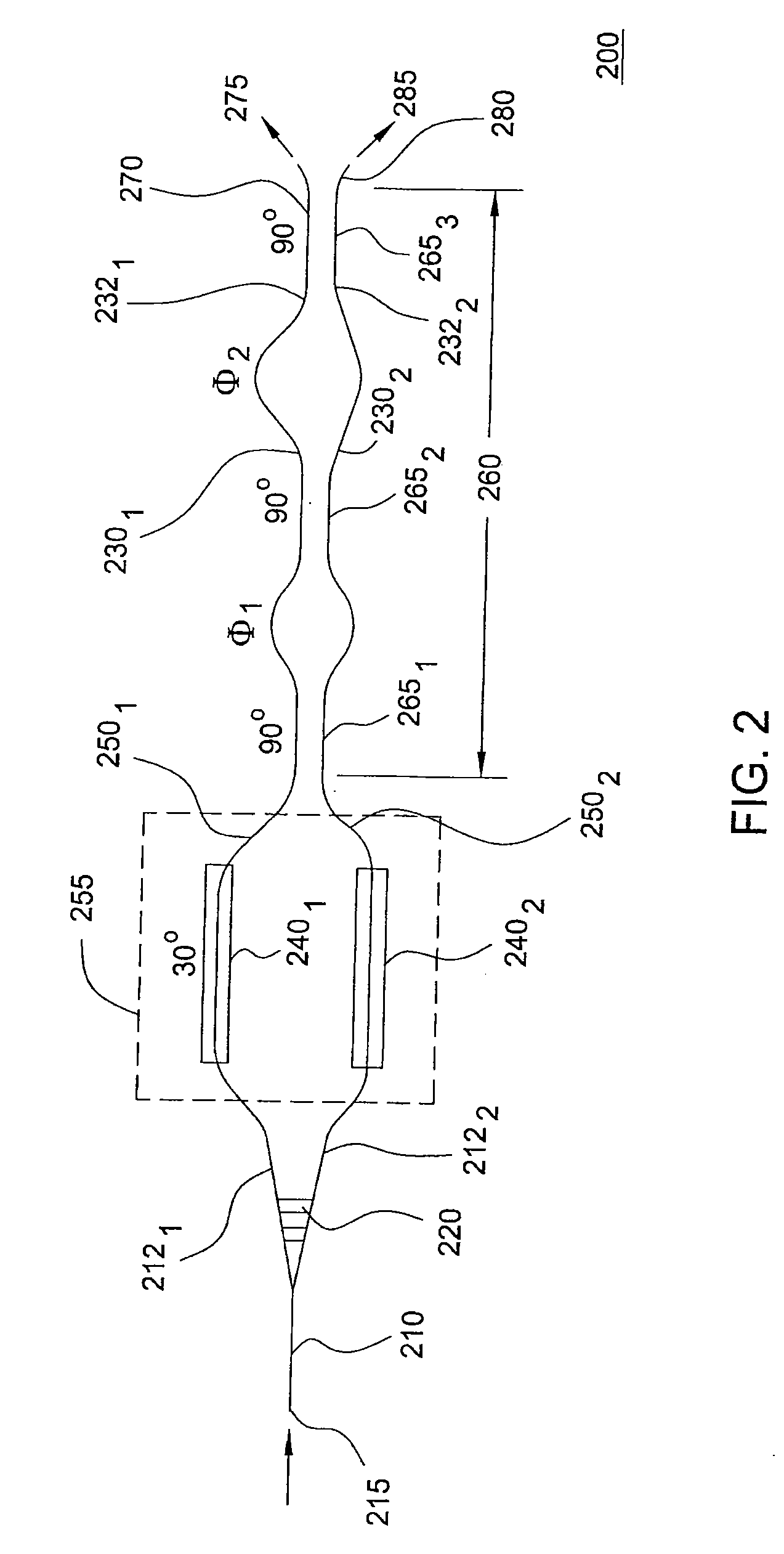
[0027] Although various embodiments of the present invention herein are being described with respect to a three-section coupler, a 1×2 optical switch and a 1×2 optical splitter, the concepts of the present invention may be applicable in various other configurations and components, such as optical switches comprising a plurality of combinations of inputs and outputs, optical power splitters comprising a plurality of combinations of inputs and outputs, and optical selectors, to name a few.

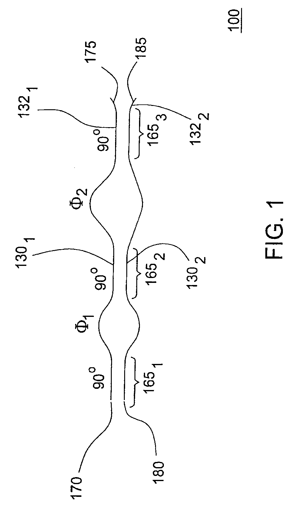
[0028]FIG. 1 depicts a high level block diagram of an embodiment of a multi-section optical coupler in accordance with the present invention. The multi-section optical coupler 100 of FIG. 1 illustratively comprises three evanescent couplers 1651, 1652 and 1653 (collectively evanescent couplers 165). The three evanescent couplers 165 are interconnected by two sets of two waveguides 1301, 1302, and 1321, 1322 comprising relative path length differences corresponding to phase differences φ1 and φ2, res...


PUM

PropertyMeasurementUnit
input lossaaaaaaaaaa
lossaaaaaaaaaa

Abstract

A proposed integrateable optical interleaver includes an input Y-branch coupler and at least two multi-section optical couplers. The multi-section optical couplers of the interleaver include at least three substantially similar optical couplers, adjacent ones of the optical couplers interconnected via at least one set of waveguides. The interleaver of the present invention comprises a highly compact and fabrication-robust form that is capable of being integrated onto a single planar lightwave circuit.

Description

CROSS-REFERENCE TO RELATED APPLICATIONS [0001] This patent application is a continuation of and claims priority to commonly-owned, co-pending U.S. patent application Ser. No. 10 / 657,862 entitled “Integrateable Optical Interleaver and De-Interleaver”, filed Sep. 9, 2003, which application is a continuation-in-part of and claims priority to commonly owned U.S. Pat. No. 6,922,507 entitled “Low-Loss Integrated Optical Coupler and Optical Switch”, filed Mar. 3, 2003, which patent claims the benefit of U.S. Provisional Application Ser. No. 60 / 360,702, filed Mar. 1, 2002; each of which is herein incorporated by reference in its entirety. The U.S. patent application Ser. No. 10 / 657,862 entitled “Integrateable Optical Interleaver and De-Interleaver”, of which this patent application is a continuation and to which this patent application claims priority, is related to U.S. Pat. No. 6,532,090 entitled “Wavelength Selective Cross-Connect With Reduced Complexity”, issued Mar. 11, 2003, and is al...

Claims


Application Information

Patent Timeline
Patent Type & Authority Applications(United States)
IPC IPC(8): G02F1/035G02B6/26G02B6/34
CPCG02B6/12021H04J14/0204H04J14/0206H04J14/0208H04J14/0209H04J14/0212H04J14/0213H04J14/0219H04J14/0221
Inventor DOERR, CHRISTOPHER RICHARDLEVY, DAVID S.
Owner LUCENT TECH INC
Learn More