
Digital broadcasting system and method

a digital broadcasting technology, applied in television systems, plural information simultaneous broadcasts, coding, etc., can solve the problems of poor reception performance in an inferior channel, almost no effect in improving the inferior reception performance, and the american type digital terrestrial broadcasting system has almost no effect in improving the reception performance. , to achieve the effect of improving the reception sensitivity

Inactive Publication Date: 2007-04-26
SAMSUNG ELECTRONICS CO LTD
View PDF15 Cites 69 Cited by
  • Summary
  • Abstract
  • Description
  • Claims
  • Application Information

AI Technical Summary

Benefits of technology

[0019] Accordingly, the present general inventive concept has been made to solve the above-mentioned and / or other problems, and an aspect of the present general inventive concept is to provide a digital broadcasting system and method capable of improving reception sensitivity of an Advanced Television Systems Committee Vestigial Sideband (ATSC VSB) way in a United States terrestrial digital television (DTV) system.

Problems solved by technology

Accordingly, its reception performance is not good in an inferior channel, and particularly, in a Doppler fading channel.
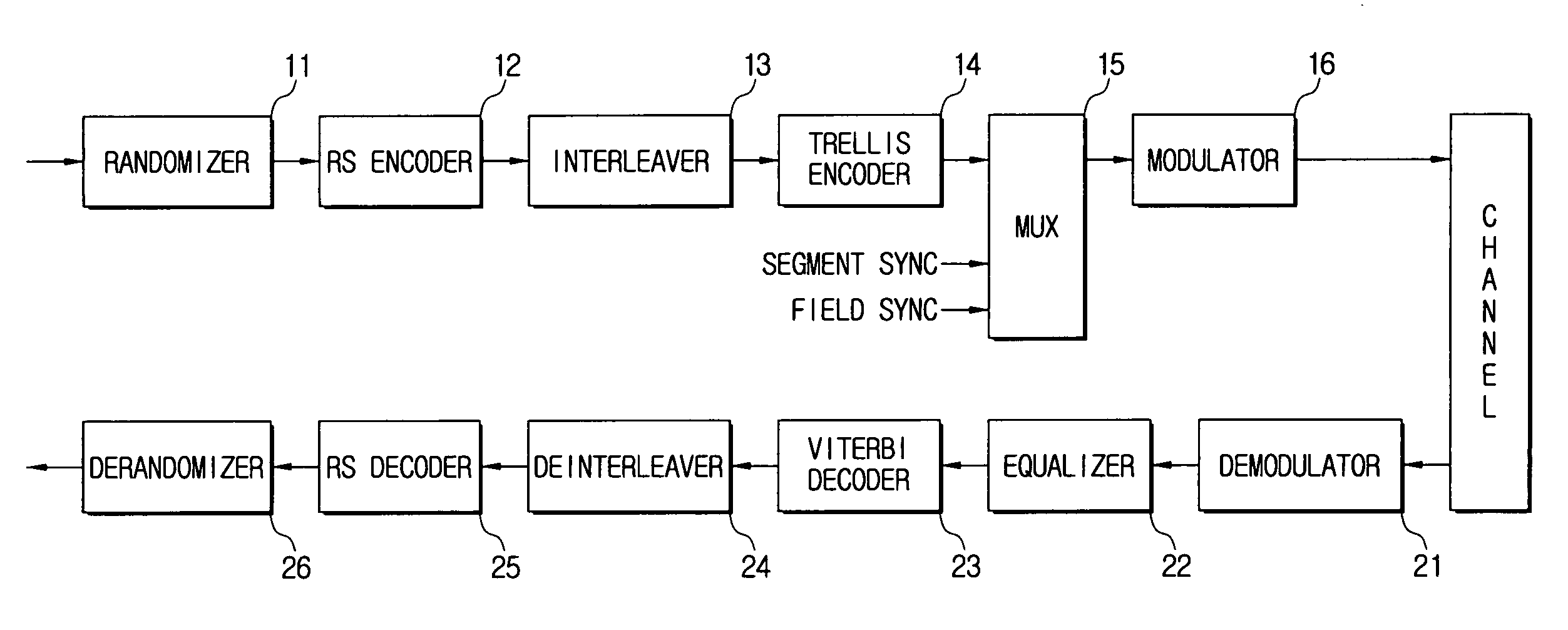
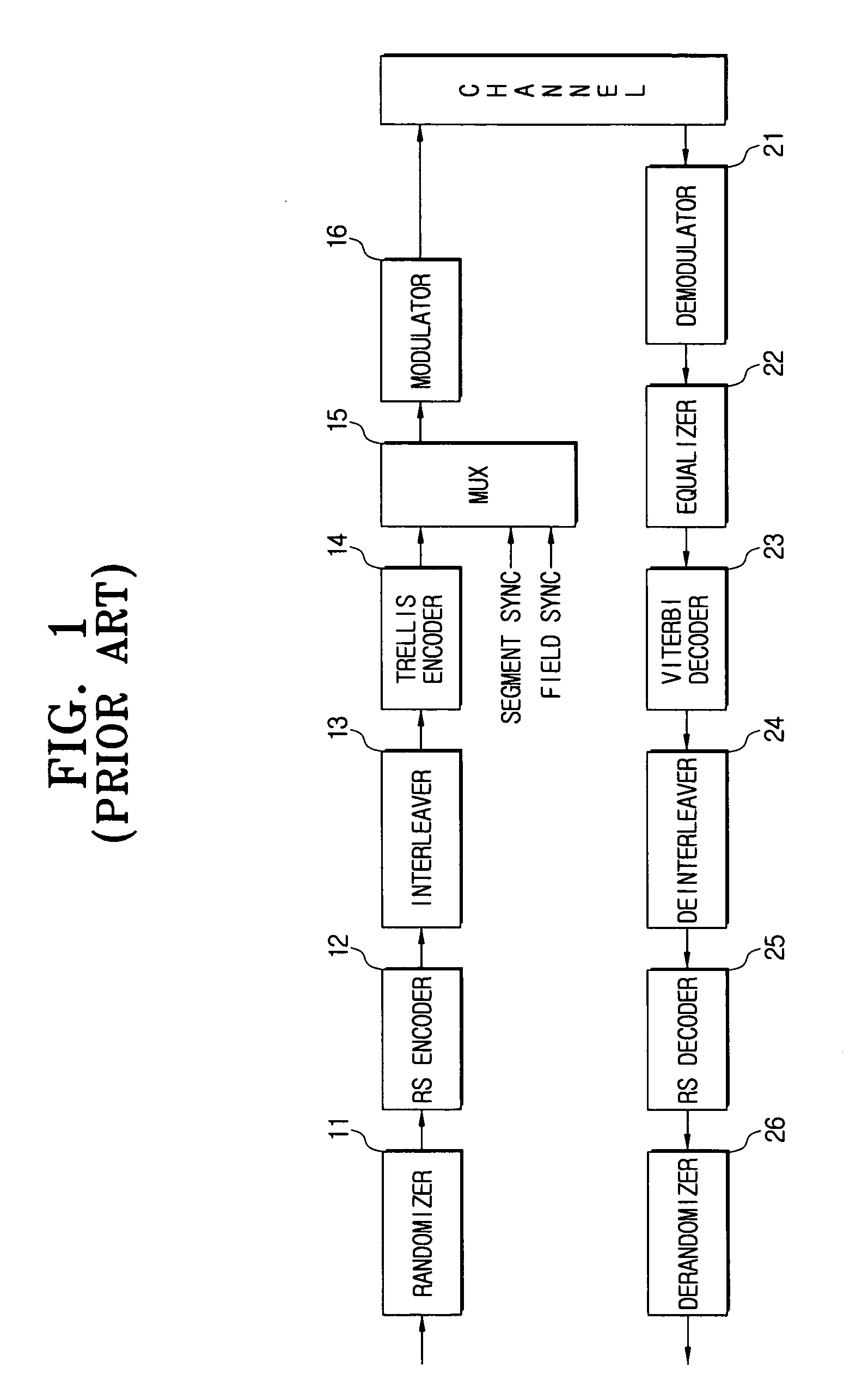
However, the American type digital terrestrial broadcasting system of FIG. 1 has almost no effect in improving the inferior reception performance in a multipath channel due to the transmission of the existing normal data, although the American type digital terrestrial broadcasting system transmits the dual stream produced by adding the robust data to the normal data.
That is, the American type digital terrestrial broadcasting system has almost no effect in improving the reception performance according to the improvement of the normal stream.
Also, even with respect to a turbo stream, it does not have a great effect in improving the reception performance in a multipath environment.
In addition, according to the conventional digital broadcasting system, it is impossible to confirm the channel state between a transmitter side and a receiver side.

Method used


Image

  • Digital broadcasting system and method
  • Digital broadcasting system and method
  • Digital broadcasting system and method

Examples


Embodiment Construction

[0069] Reference will now be made in detail to the present embodiments of the present invention, examples of which are illustrated in the accompanying drawings, wherein like reference numerals refer to the like elements throughout. The embodiments are described below in order to explain the present invention by referring to the figures.

[0070]FIG. 3 is a block diagram illustrating a configuration of a digital broadcasting system according to an embodiment of the present invention. Referring to FIG. 3, the digital broadcasting system includes a transmission stream generator 100, a transmitter 200, and a receiver 300.

[0071] The transmission stream generator 100 receives and multiplexes a normal stream and a turbo stream to generate a dual transmission stream.

[0072]FIG. 4 is a block diagram illustrating a configuration of the transmission stream generator 100 shown in FIG. 4, according to an embodiment of the present invention. Referring to FIG. 4, the transmission stream generator 1...


PUM


Abstract

A digital broadcasting system and method, where the digital broadcasting system includes: a transmission stream generator multiplexing a normal stream and a turbo stream to generate a dual transmission stream; a transmitter inserting an supplementary reference signal (SRS) into the dual transmission stream, processing the turbo stream to reconstitute the dual transmission stream, and outputting the reconstituted dual transmission stream; and a receiver receiving the reconstituted dual transmission stream, separately turbo decoding the turbo stream, inserting the turbo decode turbo stream into the dual transmission stream, and decoding the dual transmission stream into which the turbo decoded turbo stream has been inserted, to restore normal stream data and turbo stream data. Thus, reception sensitivity of a digital broadcasting signal can be efficiently improved.

Description

CROSS-REFERENCE TO RELATED APPLICATIONS [0001] This application claims the benefit of Korean Application No. 2006-68071, filed Jul. 20, 2006, in the Korean Intellectual Property Office, and U.S. Provisional Patent Application Ser. No. 60 / 728,777 filed on October 21, 2005; Ser. No. 60 / 734,295 filed on Nov. 8, 2005; Ser. No. 60 / 738,050 filed on Nov. 21, 2005; Ser. No. 60 / 739,448 filed on Nov. 25, 2005 and Ser. No. 60 / 788,707 filed on Apr. 4, 2006, in the United Sates Patent and Trademark Office, the disclosures of which are incorporated herein by reference.BACKGROUND OF THE INVENTION [0002] 1. Field of the Invention [0003] An aspect of the present invention relates to a digital broadcasting system and method using a dual transmission stream including a normal stream and a turbo stream for digital broadcasting, and more particularly, to a digital broadcasting system and method for generating and transmitting a dual transmission stream including a normal stream and a turbo stream to be ...

Claims


Application Information

Patent Timeline
IPC IPC(8): H04L27/00H04N5/44H04N5/45H04N19/89H04N21/2383H04N21/438
CPCH04L1/005H04L1/0054H04L1/0065H04L1/0066H04L1/0067H04L1/007H04L1/0071H04L1/08H04L25/0226H04L2001/0093H04N5/4401H04N5/45H04N21/2383H04N21/4382H03M13/151H03M13/1515H03M13/27H03M13/2966H04H60/07H04N21/426H04N7/015
Inventor YU, JUNG-PILJEONG, HAE-JOOPARK, EUI-JUNKIM, JOON-SOOKWON, YONG-SIKJEONG, JIN-HEECHANG, YONG-DEOKJI, KUM-RANKIM, JONG-HUN
Owner SAMSUNG ELECTRONICS CO LTD
Learn More