Curable bone substitute
a bone substitute and bone technology, applied in bone implants, tissue regeneration, prosthesis, etc., can solve the problems of significant problem, implant would not be immediately functional, bone loss, etc., and achieve the effect of promoting bone growth and limiting infection
- Summary
- Abstract
- Description
- Claims
- Application Information
AI Technical Summary
Benefits of technology
Problems solved by technology
Method used
Image
Examples
example 1
Bioplant® HTR®+HEMA
[0163] Bioplant® HTR® core was mixed with the HEMA monomer(s) for 5-7 minutes prior to addition of initiator solutions. This mixture was left for a time (set time) before adding initiators; this allows for excess monomer to settle out of the Bioplant® HTR® mixture.
[0164] Two drops of initiator composition A containing CQ / BPO in ethyl acetate (5:95) was first mixed. Two drops of initiator composition B was then incorporated into Bioplant® HTR® / monomer mixture (3-5 min), where composition B contains DMPT / EDMAB in PEG-DM (5:95). The mixture was then transferred to a mold and cured for 1 minute, unless otherwise specified. Light was provided by a Flashlite 1001t™ LED Dental Curing Light.
[0165] Bioplant® HTR® (0.2963, 0.2885, 0.2938, 0.2883, and 0.3034 g) was mixed with HEMA monomer (0.0798, 0.0768, 0.0733, 0.0761, and 0.0871 g) to provide coated core particles having 81-93% Bioplant® HTR®. The percent Bioplant® HTR® is determined after the excess monomer was allowe...
example 2
Bioplant® HTR®+PEG-DM
[0166] The procedure described in Example 1 was used for samples containing PEG-DM and HEMA monomers. In this experiment, Bioplant® HTR® (0.2725, 0.2459, 0.2542, 0.2558, and 0.2455 g) was mixed with PEG-DM (2% wt) / HEMA monomer (0.0699, 0.0664, 0.0769, 0.0714, and 0.0768 g) to provide coated core particles having 77-81% Bioplant® HTR®. The set time ranged from 0-60 seconds, with little difference noted between the trial runs. The two initiators (2 drops CQ in EA and 2 drops EDMAB in PEG-DM) were then incorporated into the mixture and mixed will (for 3-5 minutes). The mixture was then transferred to either a clean glass and cured to provide a hard polymeric substrate for each of the samples.
example 3
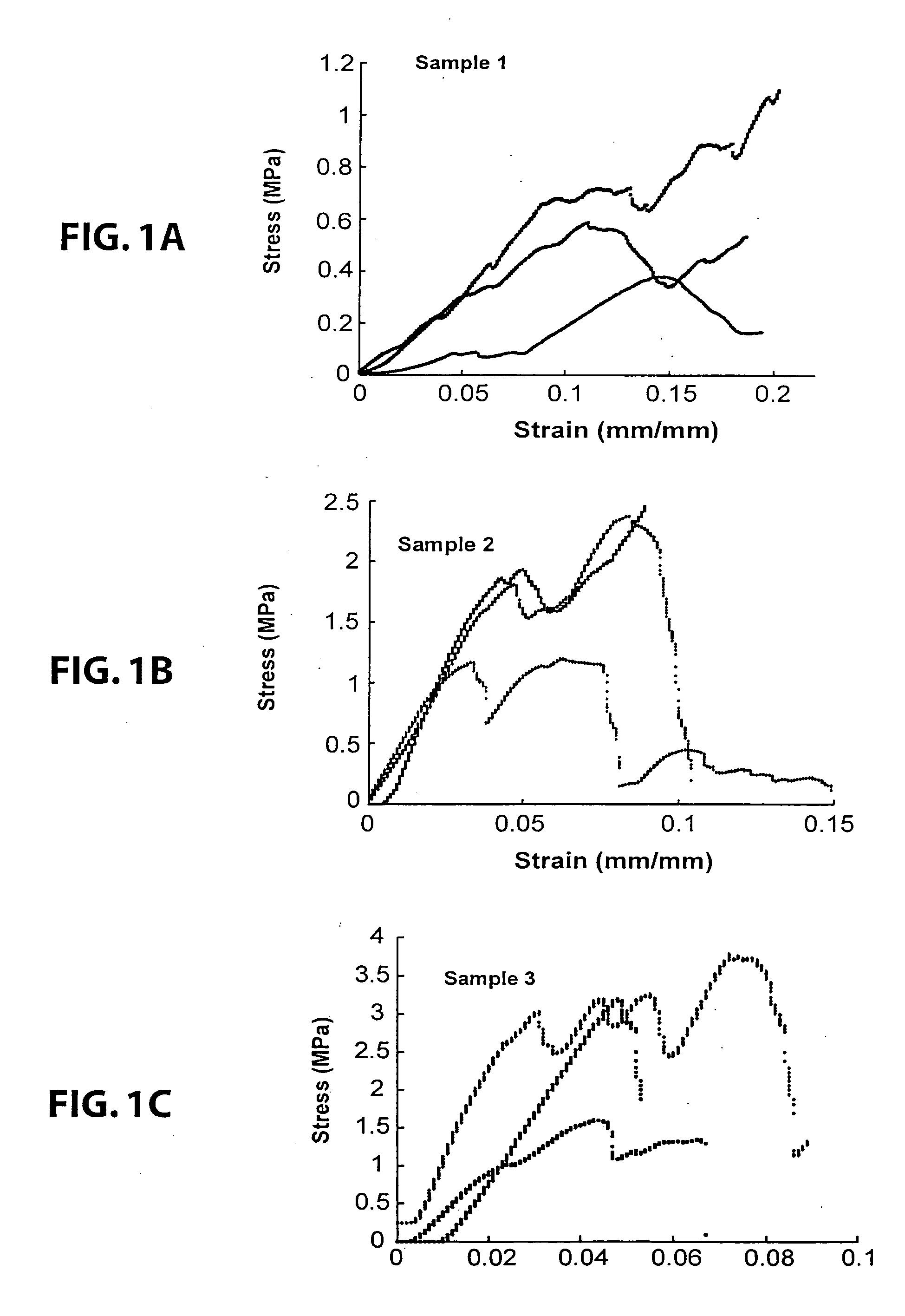
[0167] A number of different monomers (PEG-DM, HEMA, and 10% EG-DM in HEMA) were mixed with Bioplant® HTR® and the initiators were added as described in Example 1.
[0168] Initiator composition A containing CQ / BPO in ethyl acetate (5:5:90). Initiator composition B contained DMPT / EDMAB in PEG-DM (5:5:90). The mixtures were transferred to 5 mm×10 mm Teflon™ molds and cured for 1 minute with a Flashlite 1001t™ LED Dental Curing Light to form a hard material.
[0169] The first sample was made by adding 15% PEG-DMA to 85% Bioplant® HTR®.
[0170] The second polymer was made by adding 20% HEMA to 80% Bioplant® HTR®.
[0171] The third polymer was made by adding 20% of a mixture of 10% PEG-DMA and 90% HEMA to 80% Bioplant® HTR®.
PUM
| Property | Measurement | Unit |
|---|---|---|
| Fraction | aaaaa | aaaaa |
| Fraction | aaaaa | aaaaa |
| Fraction | aaaaa | aaaaa |
Abstract
Description
Claims
Application Information
 - R&D
- Intellectual Property
- Life Sciences
- Materials
- Tech Scout
- Unparalleled Data Quality
- Higher Quality Content
- 60% Fewer Hallucinations
Browse by: Latest US Patents, China's latest patents, Technical Efficacy Thesaurus, Application Domain, Technology Topic, Popular Technical Reports.
© 2025 PatSnap. All rights reserved.Legal|Privacy policy|Modern Slavery Act Transparency Statement|Sitemap|About US| Contact US: help@patsnap.com


