
Binder with expandable pouch

a technology of expandable pouches and binder covers, which is applied in the field of binder covers, can solve the problems of increasing assembly costs, increasing assembly costs, and difficulty in closing the binder, and achieves the effect of more robustness

Inactive Publication Date: 2007-04-19
MERZON ADAM
View PDF6 Cites 15 Cited by
  • Summary
  • Abstract
  • Description
  • Claims
  • Application Information

AI Technical Summary

Benefits of technology

[0010] In a preferred embodiment, each hinge is formed by a region of scores that also compresses the board in that region and between the scores. In a preferred embodiment, the scored region is formed from between five and twelve scores that are equidistantly spaced apart. Preferably, the scored region has a width of between one half inch and one and one half inches thereby permitting the hinge to more smoothly bend. By providing a wider hinge, the storage volume of the binder is advantageously increased by as much as 40% because the hinge can bend in a plurality of places to accommodate larger storage volumes. In addition, where the binder arrangement has multiple binders, each hinge can better accommodate binder ring clashing because each hinge has more give.
[0011] In a preferred embodiment, the binder arrangement is equipped with a pair of generally opposed binders that are offset such that one of the binders does not directly overlies the other one of the binders during closing thereby preventing binder ring clashing. In one preferred embodiment, one binder is offset relative to the other binder such that the one binder is spaced farther away from a centerline of the spine than the other binder.
[0013] In one preferred embodiment, the binder arrangement is configured as a case that has sidewalls extending about the outer edges of the binder covers that are releasably joined by a fastening arrangement that permits skirts of the sidewalls to be separated to enable the binder arrangement to be opened or closed. The fastening arrangement preferably is attached to the spine by a stretchable gather that preferably is of elastomeric construction. The case preferably is formed of an outer covering that is fixed to the binder covers and spine that terminates in sidewall skirts that extend outwardly beyond the peripheral edges of the binder covers. A preferred fastening arrangement is a zipper that has one end anchored to the spine by gather such that the gather stretches as needed when the zipper is being opened or closed to reduce tension at the zipper end.
[0017] Further, the binder can include a sling strap attachment which includes a pair of opposing loops attached to the outer surface of a cover, and a female connector attached at the spine. A strip has a clamp at one end and a male connector at another end. The clamp attaches to one of the loops, and the male connector connects to the female connector. A hideaway panel is attached to the outer surface of the cover for allowing the loops to be placed between the outer surface of the cover and the covering and removed from sight.
[0019] Objects, features and advantages of the invention include a binder arrangement equipped with hinges having a width and contour that permits bending to take place simultaneously at a plurality of locations thereby better accommodating binder ring clash and providing increased binder storage capacity; a binder arrangement that includes binder covers, hinges and a spine formed of a board of economical one-piece, unitary and homogenous construction; a binder arrangement that has hinges which permit bending at a plurality of pairs of locations along the hinge thereby producing a bend having a smooth radius instead of an abrupt transition; a binder arrangement with hinges that make opening and closing easier under a wide variety of binder loading conditions; a binder arrangement having a plurality of generally opposed binders that prevents, if not eliminates, binder ring clashing by offsetting one of the binders relative to the other one of the binders; a binder arrangement that is configured as a case that has a zipper end mounted to the binder arrangement by a resilient and elastomeric shock absorbing arrangement that stretches as needed to take up, transfer and absorb stresses transmitted through the zipper during case opening and closing; a binder arrangement equipped with a hold down page latch arrangement that is positively locking and that is adjustable; and a binder arrangement that is of economical construction, that is robust, that is reliable, that is long-lasting that is more durable, that is of simple construction, and which is economical to make and use.

Problems solved by technology

Unfortunately, use of a separate hinge is not only more costly to produce, but it also increases assembly costs because it requires more assembly steps.
However, such a hinge only permits the cover to bend relative to the spine along a single line.
Where the storage volume of the binder is at or greater than the storage capacity of the binder, closing the binder becomes more difficult.
In fact, repeated closings of an overfilled binder can create a crease elsewhere in one or both binder covers.
Over time, such a crease can develop into a crack that leads to premature failure of the binder cover, ultimately requiring replacement of the binder.
Unfortunately, hold down pages typically are themselves not tied down or otherwise anchored, making them largely ineffective.
In addition, hold down pages often warp, curl or become bent over time because of this.
As a result, hold down pages are often a nuisance and many times are discarded.
Unfortunately, over time, repeated openings and closings of the zipper can tear the end of the zipper from the spine or tear the zipper such that the zipper teeth will no longer properly engage thereby making it difficult, if not impossible, to close the case.
Finally, binder arrangements that have a pair of opposed binders often are difficult to close because the rings of one of the binders often interferes against the rings of the other one of the binders.
Repeated interference can cause binder rings to bend making it difficult to open and close them.
Just as bad, interference between the rings can cause creasing of one or both covers if excessive force is applied, such as what can happen out of frustration, when closing the binder arrangement.

Method used


Image

  • Binder with expandable pouch
  • Binder with expandable pouch
  • Binder with expandable pouch

Examples


Embodiment Construction

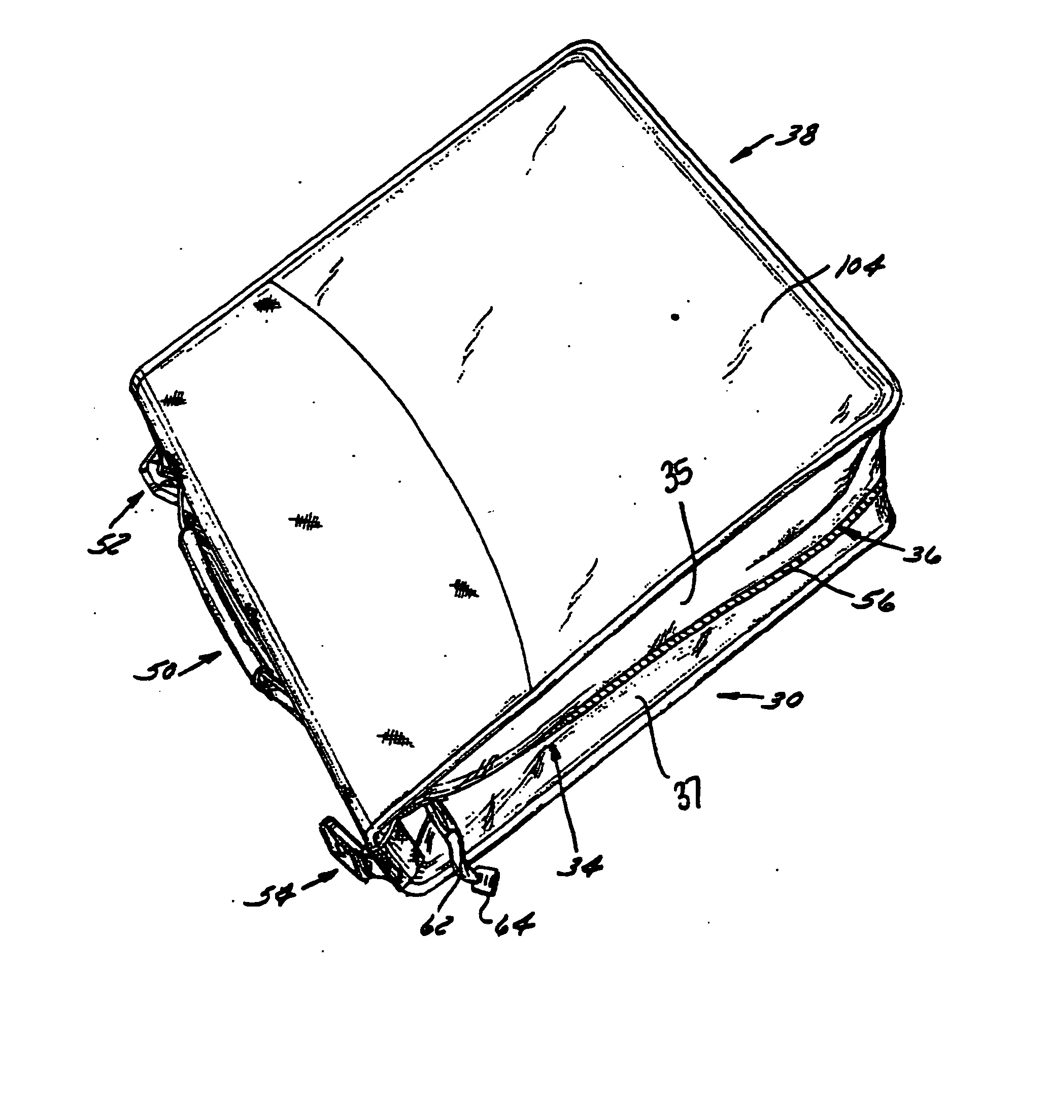
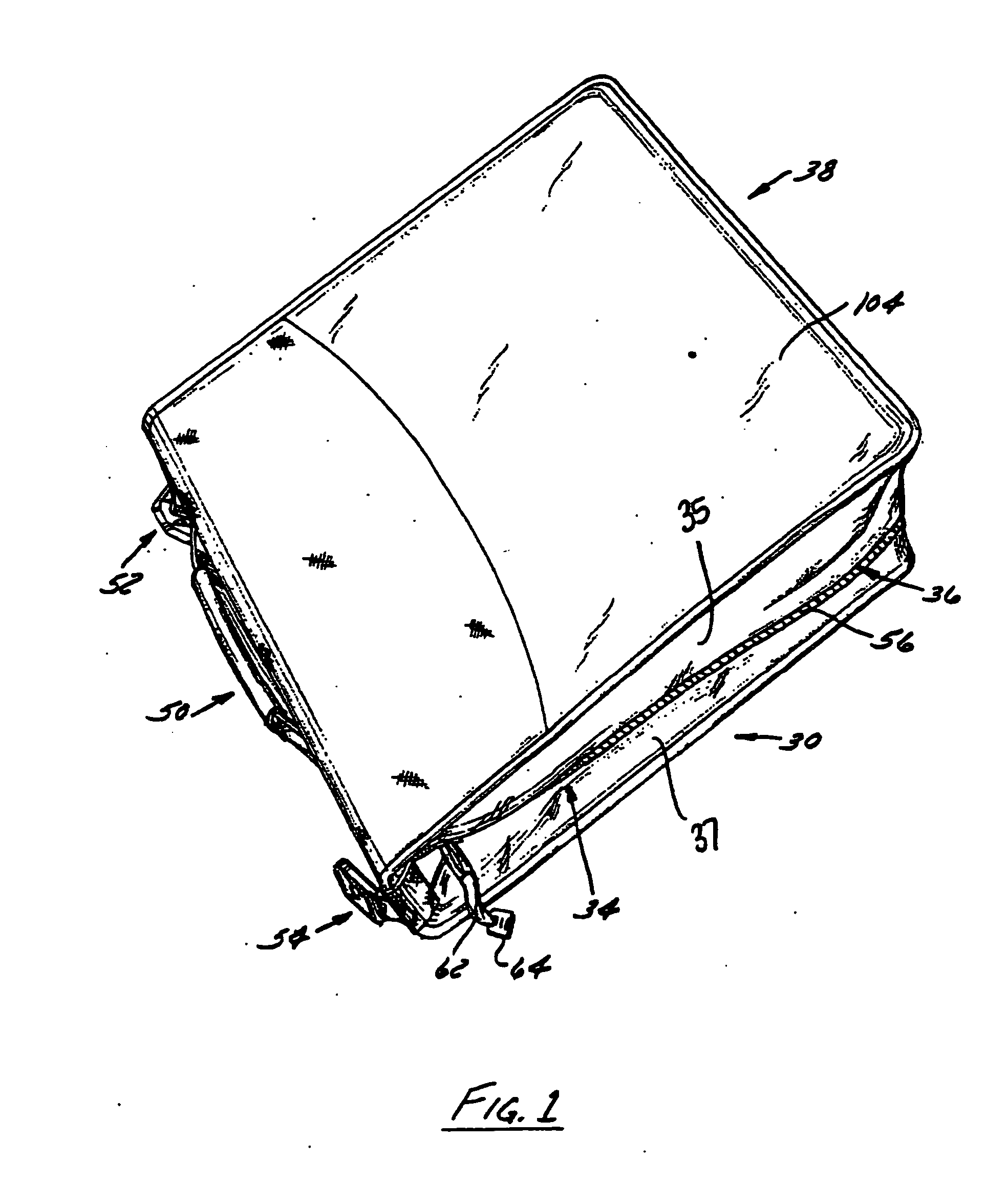
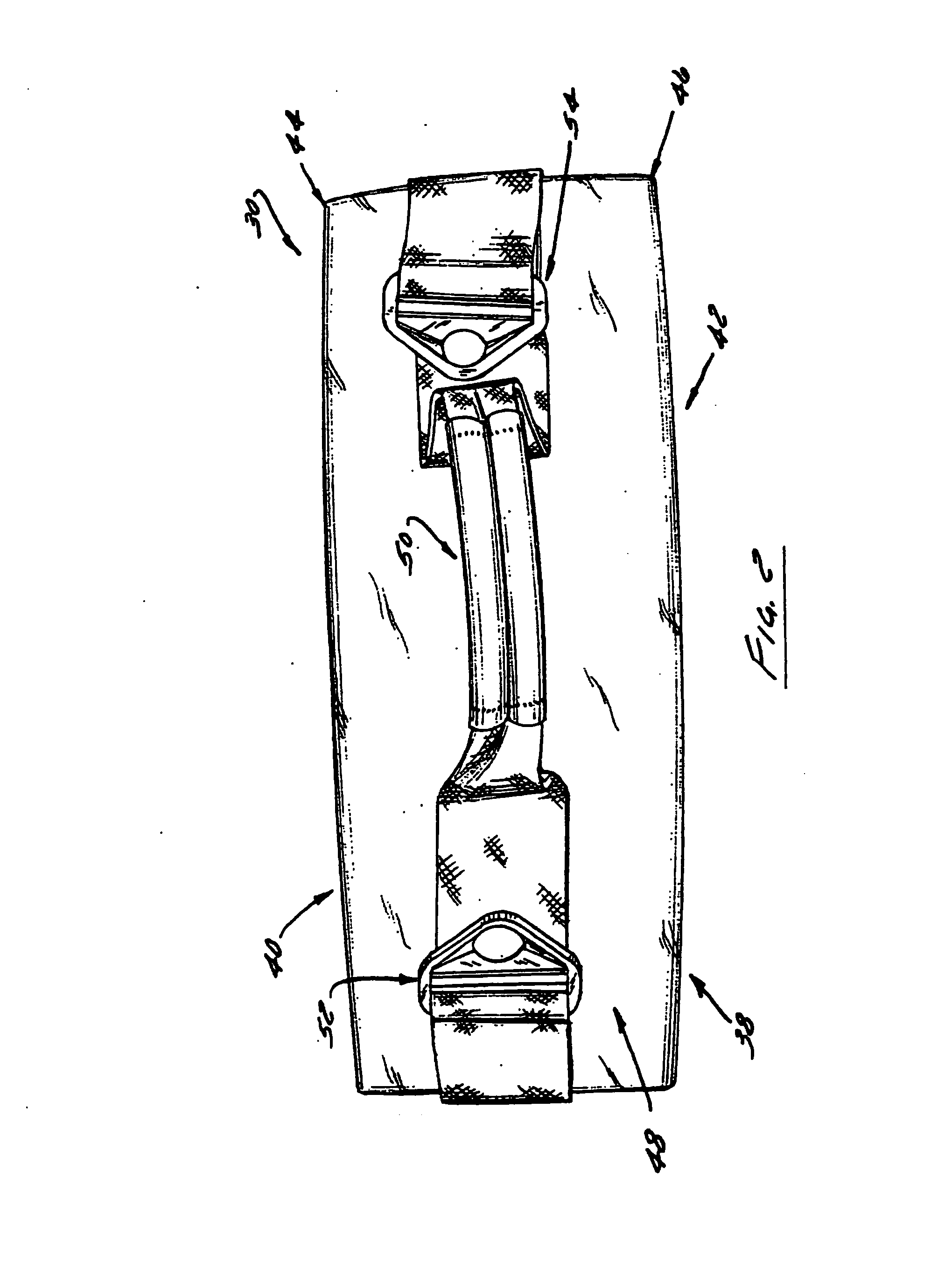
[0039]FIGS. 1-4 illustrate a preferred embodiment of a binder arrangement 30 of the invention that preferably includes at least one binder 32 (FIG. 4) and flexible fabric sidewalls 34 that retain the binder arrangement 30 in a closed position via a fastening arrangement 36. When disposed in the closed position with the fastening arrangement engaged, such as is shown in FIGS. 1-3, the binder arrangement 30 preferably forms a case 38 that houses and protects the binder contents.

[0040] The binder arrangement 30 has a front cover 40 that overlies a rear cover 42 with the front and rear covers each respectively joined by a hinge 44, 46 to a spine 48 that carries a handle 50 and a pair of strap attachment loops 52, 54. As is shown in FIG. 3, each sidewall 34 is interrupted by and releasably joined together by a fastening arrangement 36 that preferably is a zipper 56 dividing the sidewall 34 into an upper skirt 35 and lower skirt 37. To facilitate opening and closing, a slide 58 of the zi...


PUM


Abstract

A binder arrangement that has a plurality of covers hingably connected to a spine that spaces apart each cover such that each cover can carry a binder and be closed one on top of the other without either binder interfering with each other or case closure. The binder arrangement has sidewalls joined by a fastening arrangement. Further, the binder arrangement includes an expandable pouch with a cinching arrangement to allow for further expandability as well as additional support.

Description

CROSS-REFERENCE TO RELATED APPLICATION [0001] This application is a continuation-in-part of U.S. application Ser. No. 10 / 816,362 filed Mar. 31, 2004, which is incorporated herein by reference.FIELD OF THE INVENTION [0002] The present invention relates to binders, and more specifically to one or more binders that can be part a case. BACKGROUND OF THE INVENTION [0003] In the past, binder arrangements consisted of a pair of covers each joined to a spine by a hinge with at least one binder, such as a three ring binder, attached to an inside surface of one of the covers. In previous binder arrangements, the hinge was a conventional hinge that is a separate component that attaches to the spine and one of the covers. Unfortunately, use of a separate hinge is not only more costly to produce, but it also increases assembly costs because it requires more assembly steps. More recently, living hinges formed by a break or weakness in a board of one-piece construction have been used to break the ...

Claims


Application Information

Patent Timeline
IPC IPC(8): B42F13/00A45C3/02B42F3/00
CPCA45C3/02A45C7/0068A45F3/02A45F2003/142B42F13/0026B42F13/0033B42F13/38B42F13/40B42P2241/04B42P2241/06
Inventor MERZON, ADAM
Owner MERZON ADAM
Learn More