
Sensor Device for Detecting LEEG Signals and Detecting Method Thereof

Inactive Publication Date: 2007-03-29
NAT INST OF HEALTH REPRESENTED BY THE SEC OF THE DEPT OF HEALTH & HUMAN SERVICES NAT INST OF HEALTH
View PDF2 Cites 15 Cited by
  • Summary
  • Abstract
  • Description
  • Claims
  • Application Information

AI Technical Summary

Benefits of technology

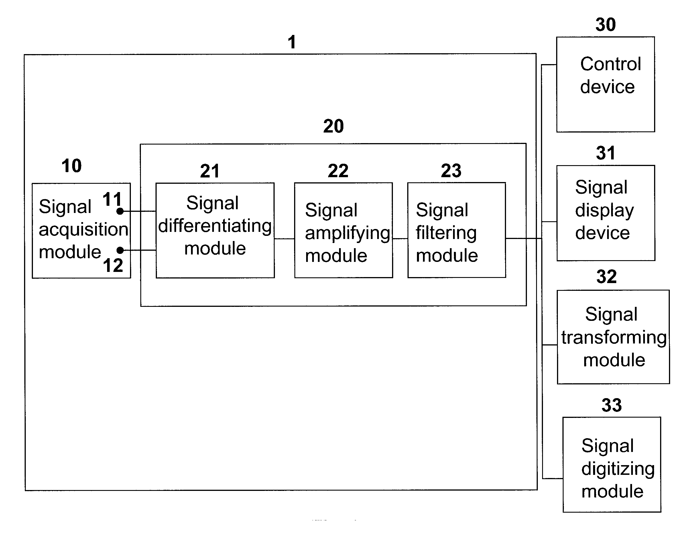
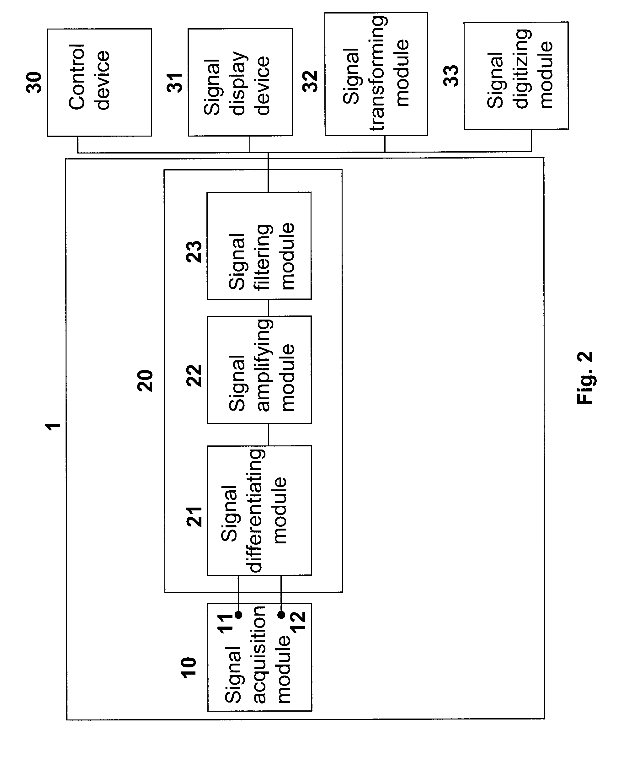
[0008] Another aspect of the invention is to provide a compact and portable sensor device for detecting an EEG signal. The sensor device includes a signal acquisition module that acquires the EEG signals and a signal differentiating module coupled to the signal acquisition module to perform a Laplacian operation on the signals acquired by the signal acquisition module based on equations including V0=Vc−Vm and Vm=V⁢ ⁢1+V⁢ ⁢2+V⁢ ⁢3+⋯+Vnn. V0 is the signal output of the signal processing module, Vc is the signal acquired by the central electrode and Vm is an arithmetic mean of signals V1-Vn acquired by the radially-arranged electrodes. The sensor device also includes a signal amplification module coupled to the signal differentiating module that amplifies a signal output of the signal differentiating module and a signal filtering module that filters an amplified signal output from the signal amplification module, so that noise signals are reduced to yield an analog Laplacian EEG signal.
[0009] A further aspect of the invention provides a compact and portable sensor device for real-time detecting EEG signal. The device comprises a central electrode coupled to a plurality of radially-arranged electrodes that acquire the EEG signal, a circuit coupled to the central electrode and the radially-arranged electrodes to subtract an average of the signals acquired by the radially-arranged electrodes from the signal acquired by the central electrode, an amplifier coupled to the circuit to amplify a signal output of the circuit and a filter coupled to amplifier in order to filter an amplified signal output of the amplifier, so that noise signals are reduced to yield an analog Laplacian EEG signal.

Problems solved by technology

However, it is difficult to mount the sensor on the scalp of the subject in case the EEG measurement is taken from the head of the subject.
Also, the signals acquired by the sensor cannot be used to directly control the prosthetic device without further offline analyses using other processing devices, such as an analog-to-digital (A / D) converter, digital signal processor (DSP), and computer system.

Method used


Image

  • Sensor Device for Detecting LEEG Signals and Detecting Method Thereof
  • Sensor Device for Detecting LEEG Signals and Detecting Method Thereof
  • Sensor Device for Detecting LEEG Signals and Detecting Method Thereof

Examples


example 1

Detection of EEG signal

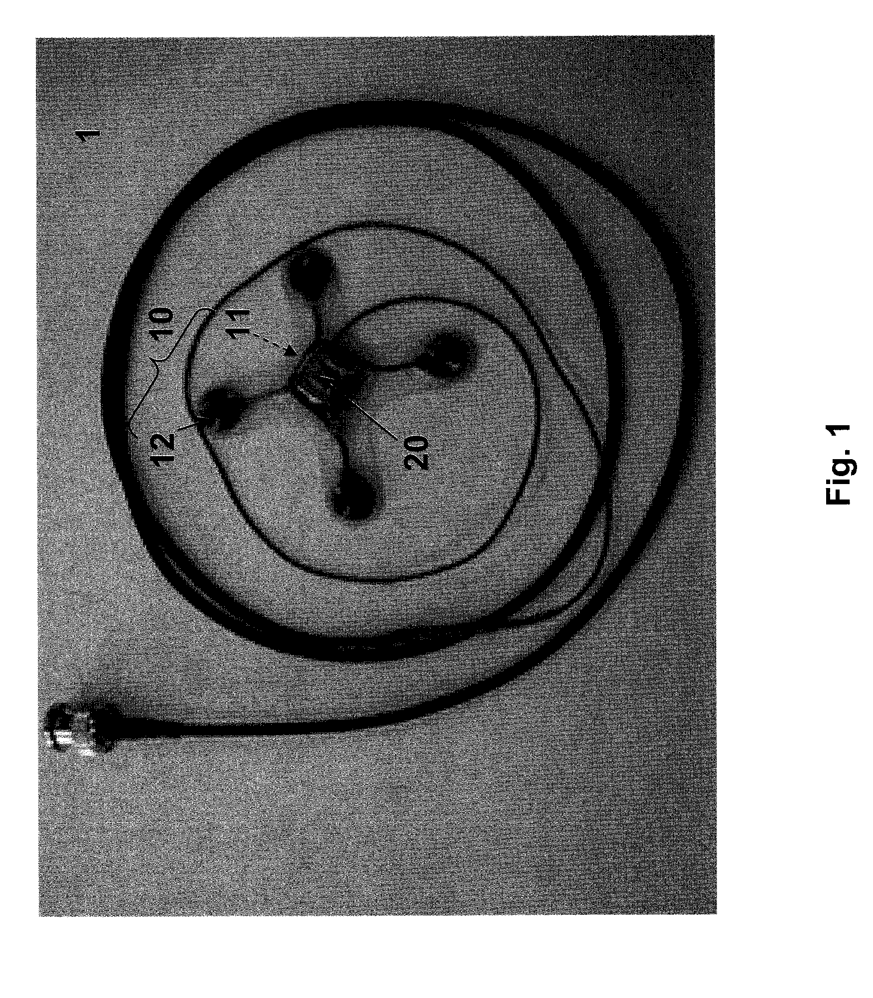
[0044] A 24 year old normal and healthy male subject without any prior history of neuromuscular disease was selected for participating in this study. According to an embodiment of the present invention, the sensor device 1 for detecting EEG signals was worn on the subject's head, with the central electrode 11 placed on the left Rolandic area, also known as sensorimotor area or so called C3 according to the international 10-20 system. The sensor device 1 comprises of five gold electrodes 12 constructed by embedding into a cross-shaped silicon rubber structure, with one surface of each electrode 12 exposed for picking up the signals. The signal electrodes 12 are placed in such a way that the central electrode 11 is placed at the center of the cross, and two pairs of the radially-arranged electrodes 12 are disposed at a distance, preferably about 3 cm away from the center of the cross. In this study, a common EEG paste was applied over a contact surface of each ...


PUM


Abstract

A sensor device that detects Laplacian electroencephalogram (LEEG) signals includes a signal acquisition module placed on a scalp of a subject to acquire brain signals. A signal processor is coupled or connected to the signal acquisition module to perform a Laplacian operation on the signals acquired by the signal acquisition module such that the noise signal is reduced to yield an analog LEEG signal with a high signal-to-noise (S / N) ratio.

Description

CROSS REFERENCE TO RELATED APPLICATION [0001] This application claims priority to U.S. Provisional Patent Application No. 60 / 720,436 filed on Sep. 26, 2005 entitled “Sensor Device for Detecting LEEG Signals and Detecting Method Thereof.”BACKGROUND OF THE INVENTION [0002] The present invention relates to the field of electrophysiology, and more particularly, to a sensor device for detecting analog Laplacian electroencephalogram (LEEG) signals and a method of detection thereof. [0003] An electroencephalogram or EEG is a brain electrical activity recorded from the scalp. The main source of EEG is the synchronous activity of thousands of cortical neurons in the brain. The EEG has been applied to a Brain-Computer Interface (BCI) field for achieving a direct interface between human and machines through the EEG without language or body actions. For example, BCI systems can allow people with severe motor disabilities to use scalp-recorded EEG activity to control a device, such as computer c...

Claims


Application Information

Patent Timeline
IPC IPC(8): A61B5/04
CPCA61B5/0478A61B5/7239A61B2562/046A61B2562/0209A61B5/291
Inventor LU, CHIH-CHENGCHEN, GIN-SHINCHEN, SHENG-FUJU, MING-SHAUNGLIN, CHOU-CHING
Owner NAT INST OF HEALTH REPRESENTED BY THE SEC OF THE DEPT OF HEALTH & HUMAN SERVICES NAT INST OF HEALTH
Learn More