Image forming apparatus
a technology of image forming apparatus and forming chamber, which is applied in the direction of electrographic process apparatus, instruments, optics, etc., can solve the problems of image defect, “deficient charging”, “blank area”, etc., and achieve the effect of suppressing image defect and high capacitan
- Summary
- Abstract
- Description
- Claims
- Application Information
AI Technical Summary
Benefits of technology
Problems solved by technology
Method used
Image
Examples
embodiment 1
[0094] (5) Embodiment 1
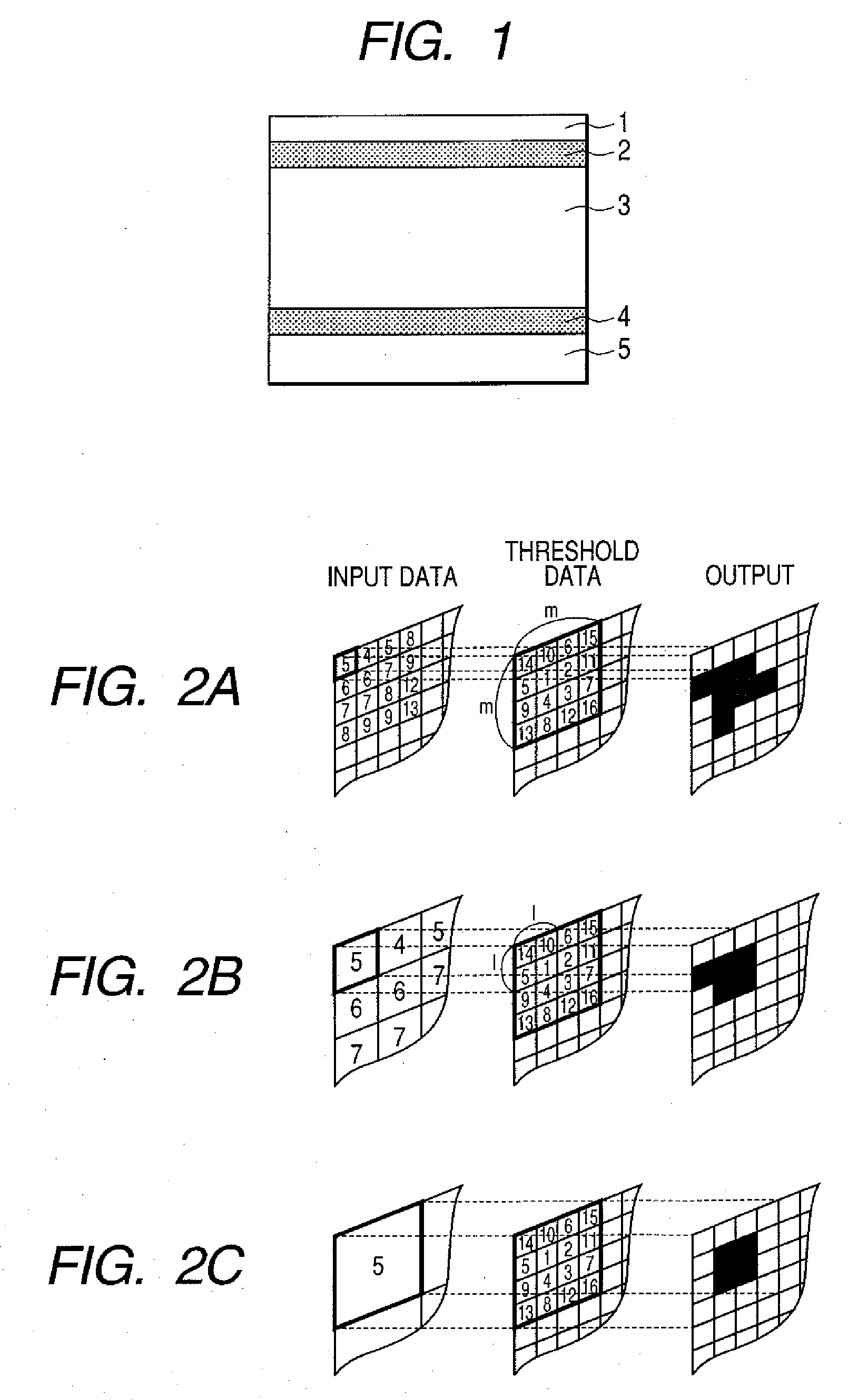
[0095] In this Embodiment 1, the development in a solid portion is executed on a latent image of an irregularity structure, obtained by a screen (line) process that has ordinarily been employed in a highlight portion and a medium tone portion. In such development, there is employed toner of a same amount as in the development of a solid portion in the conventional method. It is therefore featured in realizing, in a solid portion, an irregularity structure having a higher toner layer and including also an air layer in addition to the toner layer.
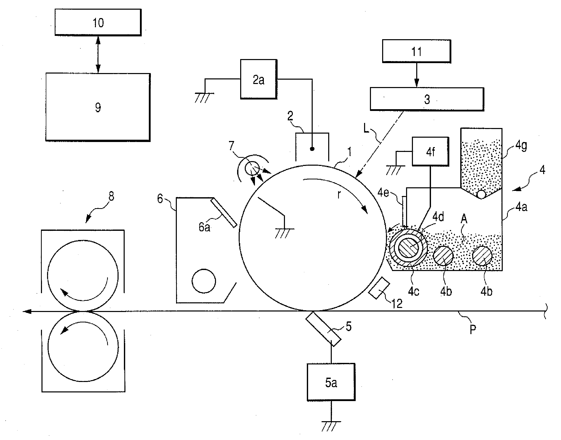
[0096] Result of investigation will be explained. As the testing apparatus, there was employed a modified iRC-6800 apparatus, utilizing a digital image exposure process and a reversal developing process. The used image bearing members include an organic photoreceptor and an α-Si photoreceptor, explained below. The organic photoreceptor had a film thickness dm of 28 μm, a relative permittivity εm of 3.3, and a capacitan...
embodiment 2
[0114] (6) Embodiment 2
[0115] In Embodiment 2, an investigation was made without a complete interspacing (thinning) in the Embodiment 1 of the toner image on the image bearing member. More specifically, in the solid portion employed in Embodiment 1 (line-space resolution of 600 dpi), the laser beam was so modulated as to execute an irradiation with a lowered intensity even in a portion corresponding to a white background portion formed by spaces. Thus a toner layer was formed even in a recessed portion in the irregularity structure of the toner layer. Results are shown in FIG. 19. It was confirmed that the toner layer on the image bearing member had an irregularity structure, without a complete interspacing (thinning). More specifically, toner is not formed in the recessed portion in Embodiment 1, while toner is formed in the recessed portion in Embodiment 2. A measured charging efficiency, a difference dt′ between a toner layer height in the recessed portion and a toner layer heigh...
embodiment 3
[0120] (7) Embodiment 3
[0121] In contrast to Embodiment 1 (utilizing a screen structure formed by lines), Embodiment 3 employed a screen structure, formed by dots, for the development in the solid portion. Other conditions were same as those in Embodiment 1. Table 9 shows results of comparison of a 2-dot-1-space process with the 2-line-1-space process in Embodiment 1, and comparison of a 3-dot-1-space process with the 3-line-1-space process in Embodiment 1. The 2-dot-1-space process is executed by turning on the laser beam continuously for 2 dots and then turning off for 1 dot in repetition along the main scanning direction of the photosensitive member, and the 3-dot-1-space process is executed by turning on the laser beam continuously for 3 dots and then turning off for 1 dot in repetition along the main scanning direction of the photosensitive member. Thus, the number of spaces in this case means a number of turn-offs of the laser beam in the main scanning direction. A number of s...
PUM
 Abstract
Description
Claims
Application Information
 - R&D
- Intellectual Property
- Life Sciences
- Materials
- Tech Scout
- Unparalleled Data Quality
- Higher Quality Content
- 60% Fewer Hallucinations
Browse by: Latest US Patents, China's latest patents, Technical Efficacy Thesaurus, Application Domain, Technology Topic, Popular Technical Reports.
© 2025 PatSnap. All rights reserved.Legal|Privacy policy|Modern Slavery Act Transparency Statement|Sitemap|About US| Contact US: help@patsnap.com


