
Electroplating apparatus based on an array of anodes

an array and array technology, applied in the field of electrochemical devices based on arrays of anodes, can solve the problems of high resistance, large amount of conductive seed layers formed on the substrate, and features on some portions of the substrate may be undesired or even filled up

Inactive Publication Date: 2007-03-29
APPLIED MATERIALS INC
View PDF18 Cites 75 Cited by
  • Summary
  • Abstract
  • Description
  • Claims
  • Application Information

AI Technical Summary

Benefits of technology

[0015] The details of one or more implementations are set forth in the accompanying drawings and the descript

Problems solved by technology

However, with conventional ECP processes and systems, the conductive seed layer formed on the substrate is generally very thin, and as such, is highly resistive.
This phenomenon is generally known as the “terminal effect”, and is an undesirable characteristic associated with conventional plating systems.
Another challenge in an electrochemical process is that features on some portions of a substrate may be undesirably filled or even filled up while immersing the substrate into a plating bath.
During this time period, which may be as little as 0.25 seconds, some features in certain region on the substrate may be filled which may result in poor uniformity and variable device yield performance.
Because substrates are rotated about the same axis of the concentric anode rings, areas corresponding to the region between the anode rings are not exposed enough to the anode rings resulting in another form of non-uniformity.
Furthermore, the concentric anode rings can only provide symmetrical bias patterns which are not effective to compensate for the non-uniformity generated during an immersing process.

Method used


Image

  • Electroplating apparatus based on an array of anodes
  • Electroplating apparatus based on an array of anodes
  • Electroplating apparatus based on an array of anodes

Examples


Embodiment Construction

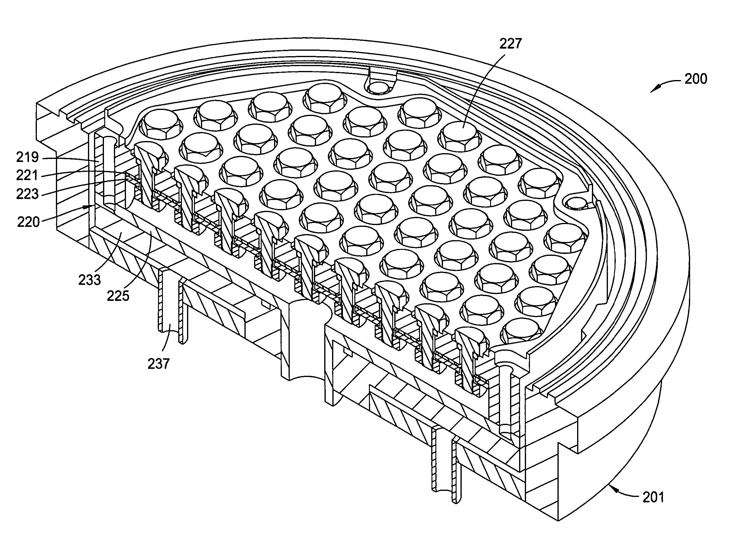
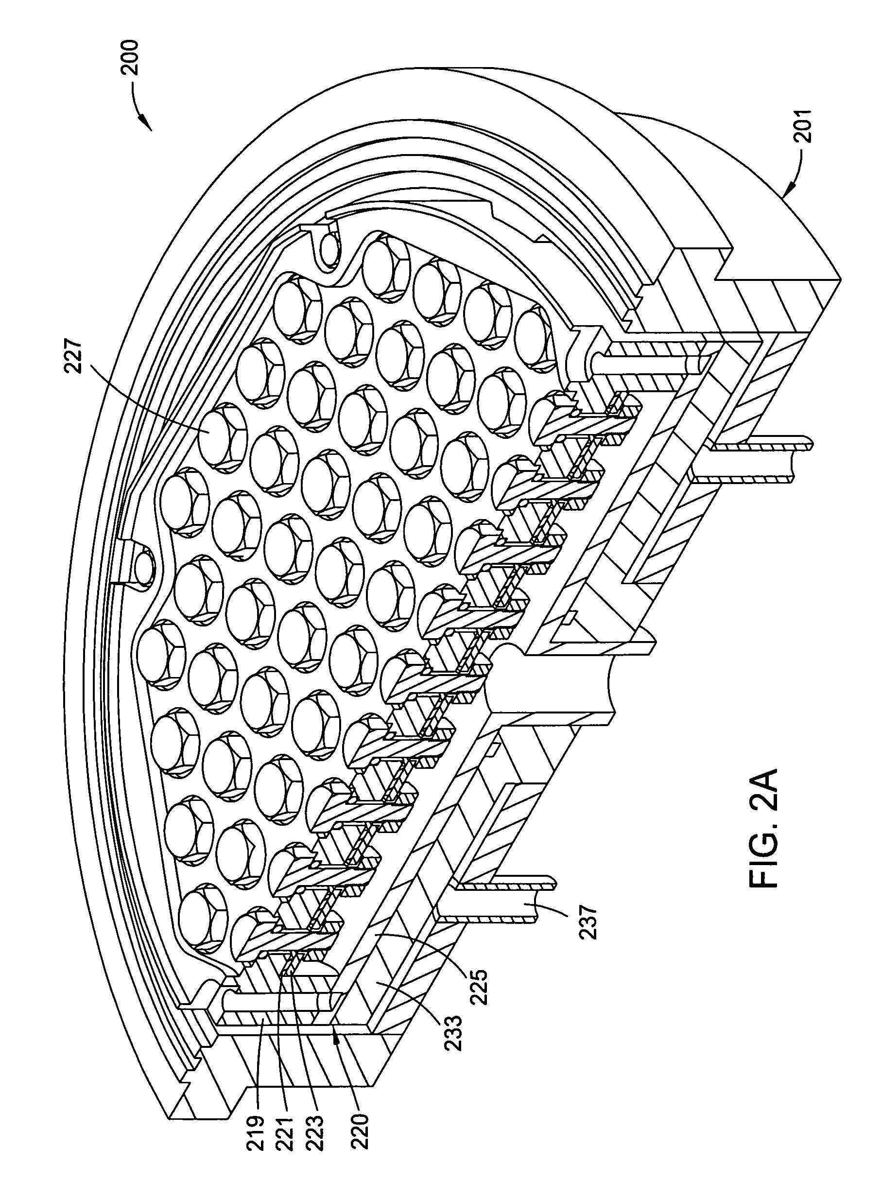
[0043] Embodiments of the present invention generally provide an anode assembly to be used in an electroplating cell. The anode assembly generally comprises an array of anode elements which can be biased independently and act as individual anodes. The present invention also provides an electroplating cell having the anode assembly of the present invention disposed therein.

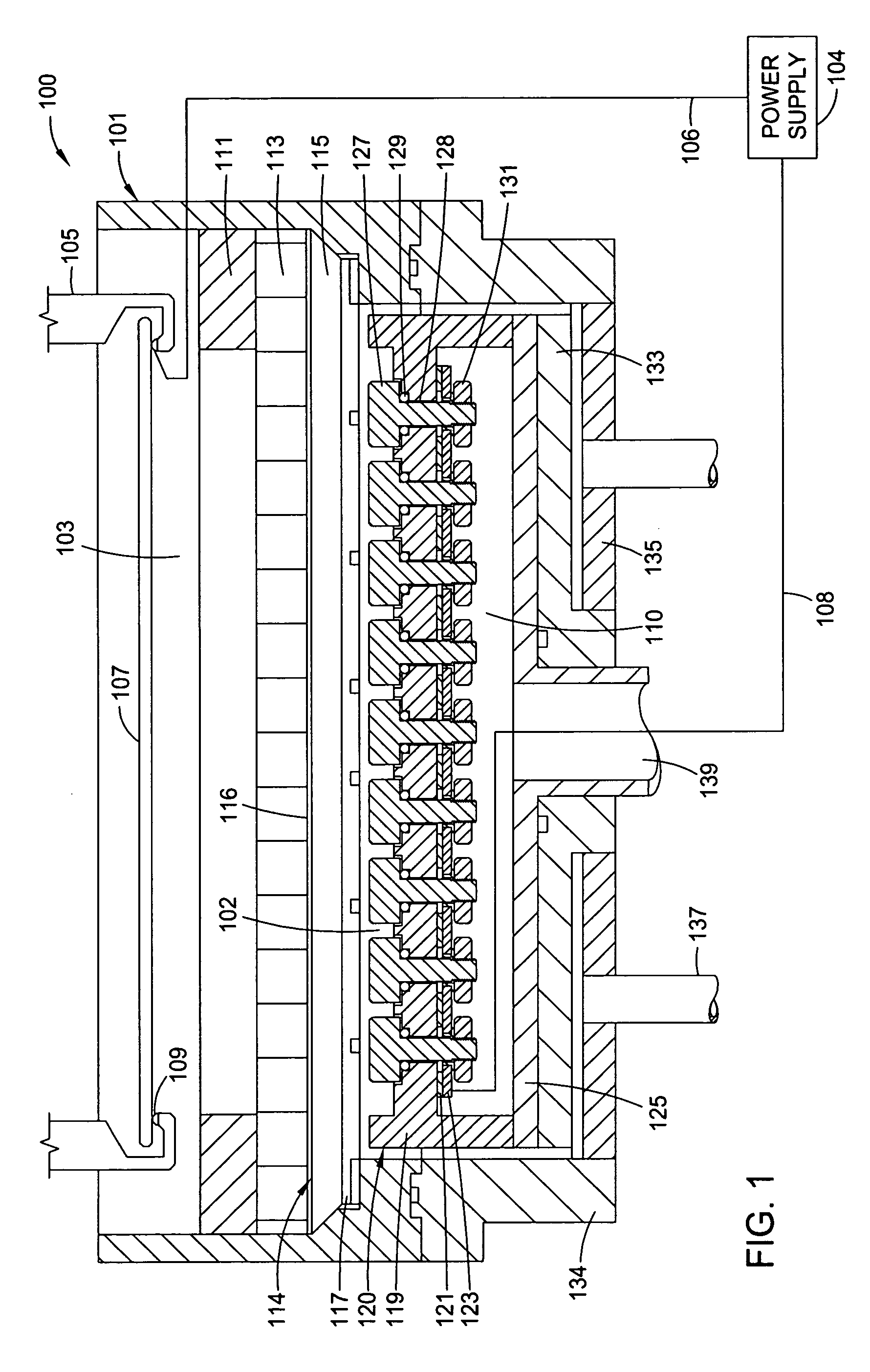
[0044]FIG. 1 illustrates a schematic sectional view of an exemplary plating cell of the present invention. The electrochemical plating cell 100 generally includes a basin assembly 101 configured to contain a plating solution that is used to plate a metal, e.g., copper, onto a substrate 107 during an electrochemical plating process. During the plating process, the plating solution is generally continuously supplied to the basin assembly 101, and therefore, the plating solution continually overflows out of the basin assembly 101 and is collected and drained for chemical management and / or recirculation.

[0045] The ba...


PUM

PropertyMeasurementUnit
Poweraaaaaaaaaa
Electrical conductoraaaaaaaaaa

Abstract

The present invention generally relates to apparatus and methods for plating conductive materials on a substrate. One embodiment of the present invention provides an apparatus for plating a conductive material on a substrate. The apparatus comprises a fluid basin configured to retain an electrolyte, a contact ring configured to support the substrate and contact the substrate electrically, and an anode assembly disposed in the fluid basin, wherein the anode assembly comprises a plurality of anode elements arranged in rows.

Description

CROSS-REFERENCE TO RELATED APPLICATIONS [0001] This application claims benefit of U.S. Provisional Patent Application Ser. No. 60 / 684,444 filed May 25, 2005, which is herein incorporated by reference.BACKGROUND OF THE INVENTION [0002] 1. Field of the Invention [0003] Embodiments of the invention generally relate to electroplating cells having an array of anode elements which may be biased independently. [0004] 2. Description of the Related Art [0005] In semiconductor processing, electrochemical plating (ECP) is generally the preferred technique for filling features formed on substrates with a conductive material. A typical ECP process generally includes immersing a substrate into an electrolyte solution that is rich in ions of the conductive material (generally copper), and then applying an electrical bias between a conductive seed layer formed on the surface of the substrate and an anode positioned in the electrolyte solution. The application of the electrical bias between the seed...

Claims


Application Information

Patent Timeline
IPC IPC(8): C25D17/00
CPCC25D17/10Y10S204/07H01L21/2885C25D17/12
Inventor SINGH, SARAVJEETBIRANG, MANOOCHERKOVARSKY, NICOLAY Y.ROSENFELD, ARON
Owner APPLIED MATERIALS INC
Learn More