Hybrid Electric Vehicle

Inactive Publication Date: 2007-03-29
CARNAHAN ERIC SCOTT
View PDF0 Cites 30 Cited by
  • Summary
  • Abstract
  • Description
  • Claims
  • Application Information

AI Technical Summary

Benefits of technology

[0009] The present invention includes a special type of turbine engine that utilizes the exhaust gas from the vehicle's internal combustion engine as both the working fluid and power source of the turbine. The turbine creates power by expanding the exhaust gas from the ICE adiabatically through an expansion turbine from the pressure at which the exhaust gas leaves the engine to a sub-atmospheric pressure. The expanded exhaust gas is then passed through a heat exchanger where it is cooled. The cooled exhaust gas is then compressed back to ambient pressure by a compressor and expelled from the turbine. Because the exhaust gas has been cooled before it entered the compressor it is at a denser state than it was after it left the turbine, and because it is denser, the compression process requires less work than the amount of work that is produced by the expansion process. Thus, the turbine engine produces a net work output. The turbine engine can be constructed with one or more cooling and compression stages. Having more than one cooling and compression stage can increase the efficiency of the turbine because the average temperature of the gas during the compression process will be reduced which will increase the density of the gas and reduce the amount of work required to compress it.
[0011] It is a further goal of a preferred embodiment of the invention to more efficiently harness the thermal energy created inside the ICE by minimizing or eliminating the unrestrained expansion of exhaust gasses exiting the engine cylinders. Typically when the exhaust valve of an ICE opens, the gas within the cylinder is still at a pressure that is above atmospheric pressure. Thus the gas within the cylinder expands in an unrestrained fashion until the pressure within the cylinder has reached the pressure of the gas within the exhaust manifold. This unrestrained expansion is inefficient because no work is harnessed by the engine from the gas during the unrestrained expansion process.
[0013] This arrangement will decrease the power output from the ICE because the engine must do more work to expel the exhaust gas from the engine. However it will increase the power output of the expansion turbine by a larger amount and thus increase the total power output of the combined engines for a given amount of fuel consumed.

Problems solved by technology

This unrestrained expansion is inefficient because no work is harnessed by the engine from the gas during the unrestrained expansion process.

Method used


Image

  • Hybrid Electric Vehicle
  • Hybrid Electric Vehicle
  • Hybrid Electric Vehicle

Examples


Embodiment Construction

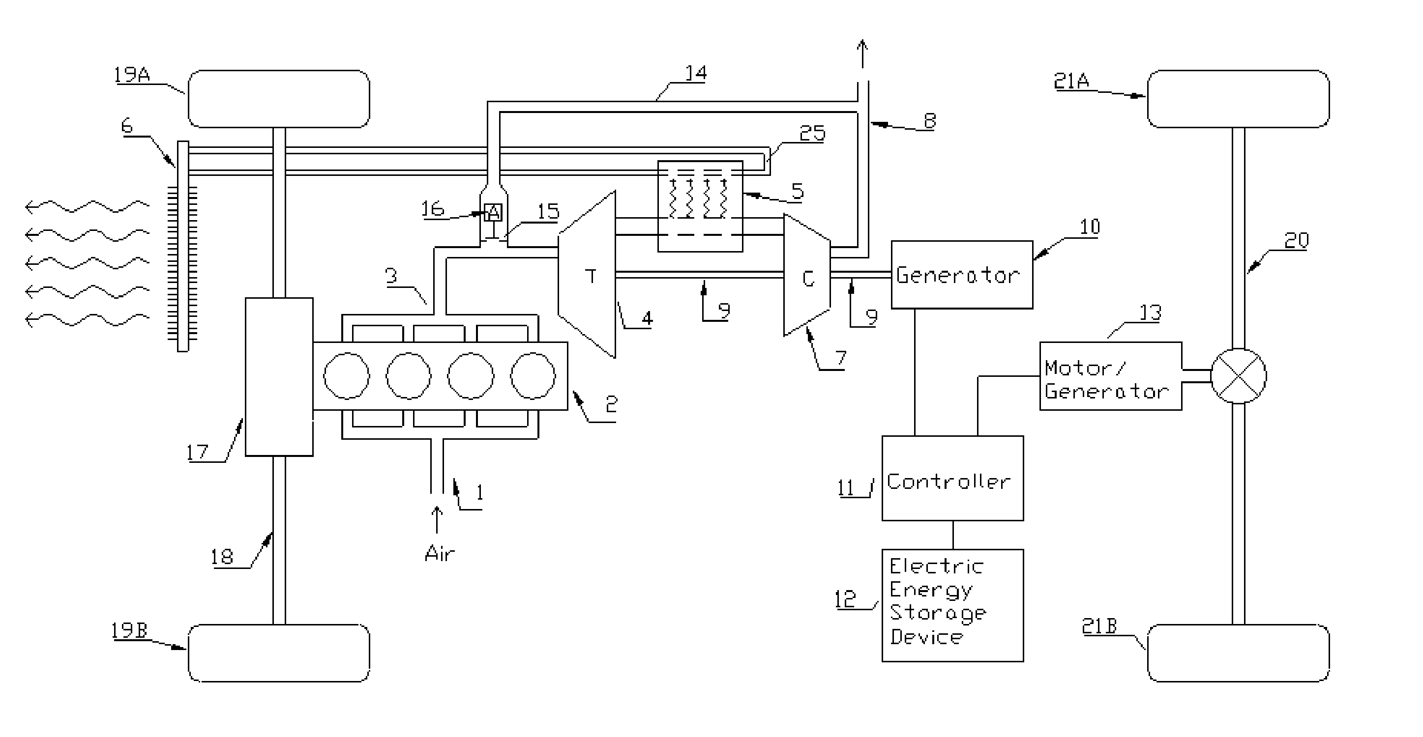
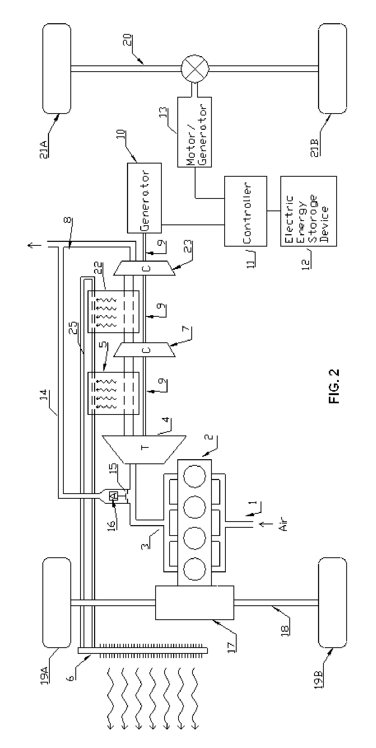
[0020] In describing the preferred embodiment and an alternate embodiment of the present invention, as illustrated in FIGS. 1-2, specific terminology is employed for the sake of clarity. The invention, however, is not intended to be limited to the specific terminology so selected, and it is to be understood that each specific element includes all technical equivalents that operate in a similar manner to accomplish similar functions.

[0021] Referring now to FIG. 1, air enters the intake manifold 1 of the internal combustion engine 2. A transmission 17 transfers power from engine 2 to front axel 18. Front axle 18 transfers power from transmission 17 to the front wheels 19A and 19B. The exhaust gas exits engine 2 through the exhaust manifold 3 and enters the expansion turbine 4 where it expands adiabatically to a sub atmospheric pressure. Upon exiting expansion turbine 4, the exhaust gas enters a heat exchanger 5 where it is cooled. A cooling fluid 25 is preferably circulated continuou...


PUM


Abstract

A hybrid electric vehicle having an internal combustion engine as its primary power source and a turbine engine that is powered by waste heat from the internal combustion engine as an additional power source.

Description

TECHNICAL FIELD [0001] The present invention relates generally to hybrid electric vehicles and to external heat engines, which can convert thermal energy contained within a hot gas into mechanical energy. BACKGROUND OF THE INVENTION [0002] It is well known to construct a hybrid electric vehicle (hereinafter abbreviated HEV) that utilizes an internal combustion engine (hereinafter abbreviated ICE), an electric generator and an electric motor. HEVs have been built in a huge variety of different configurations. [0003] In some HEVs an ICE drives a generator that generates electricity, which powers an electric motor that drives the wheels. In other HEVs (sometimes called mild HEVs) the ICE and the electric motor are configured such that both the engine and motor can be used to drive the wheels at the same time. [0004] HEVs are usually more efficient than vehicles that are powered only by ICEs because ICEs are typically not very efficient over a broad range of operating conditions. They a...

Claims


Application Information

Patent Timeline
IPC IPC(8): B60K1/00
CPCB60K6/44B60K6/52Y02T10/6265Y02T10/623B60K17/356B60L15/20B60L15/2045B60L2260/26B60L2260/28Y02T10/72B60L50/40B60L50/61B60L50/16B60L58/21Y02T10/62Y02T10/64Y02T10/70Y02T10/7072
Inventor CARNAHAN, ERIC SCOTT
Owner CARNAHAN ERIC SCOTT
Why Eureka
Try Eureka