Hard disk drive with mechanism for controlling protrusion of head

Inactive Publication Date: 2007-03-22
WESTERN DIGITAL TECH INC
View PDF5 Cites 13 Cited by
  • Summary
  • Abstract
  • Description
  • Claims
  • Application Information

AI Technical Summary

Benefits of technology

[0013] The present invention has been made to allow effective suppression of collisions between the magnetic disk and the head element section of the head slider regardless of the recession of the head element section subject to variation due to process fluctuations.
[0014] According to a first aspect of the present invention, there is provided a data storage apparatus which comprises: a head slider comprising a slider and a head element section wherein the head element section is recessed from the slider when viewed from a magnetic disk; a controller which refers to preliminarily registered data and determines the magnitude of current to be supplied to a heating element capable of changing the protrusion of the head element section wherein the registered data represents a magnitude of current appropriate for the recession level of the head element section; and a current supply circuit which supplies a current to the heating element according to the determination of the controller. Since the magnitude of current to be supplied to the heating element capable of changing the protrusion of the head element section is determined by referring to the registered data representing an appropriate magnitude of current for the recession level of the head element section, it is possible to effectively suppress collision between the head element section and the magnetic disk even if the recession level differs among head sliders due to process fluctuations.
[0015] According to a second aspect of the present invention, there is provided a data storage apparatus according to the above-mentioned first aspect, wherein the heating element is a heater to adjust the protrusion of the head element section and the current to the heating element is a heater current which flows along the heater. By the heater, it is possible not only to raise the performance by protruding the head element section but also to effectively suppress collision between the head element section and the magnetic disk even if the recession level differs among head sliders due to process fluctuations.

Problems solved by technology

It is difficult to form these tiny bumps uniformly in height.
That is, it is difficult to completely remove abnormally high bumps.
In the case of a head element section using a magnetoresistive effect transducer, if an abnormally high bump touches the head element section, this contact raises the temperature of the element section due to frictional heat, which temporally changes the resistance and therefore causes an abnormality in the read signal.
Further, it is possible that the magnetic head itself may be damaged if the magnetic head makes harsh contact with a tiny bump.
In terms of magnetic read / write, however, this technique causes more deterioration in performance if the recession of the device element section is enlarged since the clearance between the head device section and the magnetic disk becomes larger although thermal asperities can be suppressed.
In addition, in a comparison between a head slider having a small recessed head element step on a slider and a large flying height and a head slider having a larger recessed head element step on a slider and a small flying height, it is more difficult for the former than the latter to judge whether the head element section is protruded beyond the slider surface faced toward the magnetic disk when the thermal expansion element is energized and expanded for write or read.
Therefore, this technique is not effective for new bumps grown from defects on the magnetic disk and dust particles inhaled between the head slider and the magnetic disk during the operation of the magnetic disk drive.
The risk of the head element section being damaged by contact with such bumps and particles is not yet eliminated.

Method used


Image

  • Hard disk drive with mechanism for controlling protrusion of head
  • Hard disk drive with mechanism for controlling protrusion of head
  • Hard disk drive with mechanism for controlling protrusion of head

Examples


Embodiment Construction

[0036] Embodiments of the present invention will be described below. For clear understanding, omission and simplification are made where appropriate in the following description and the drawings. In addition, where the same component appears in another drawing, the same reference numeral is given and its description is omitted for the purpose of clear understanding.

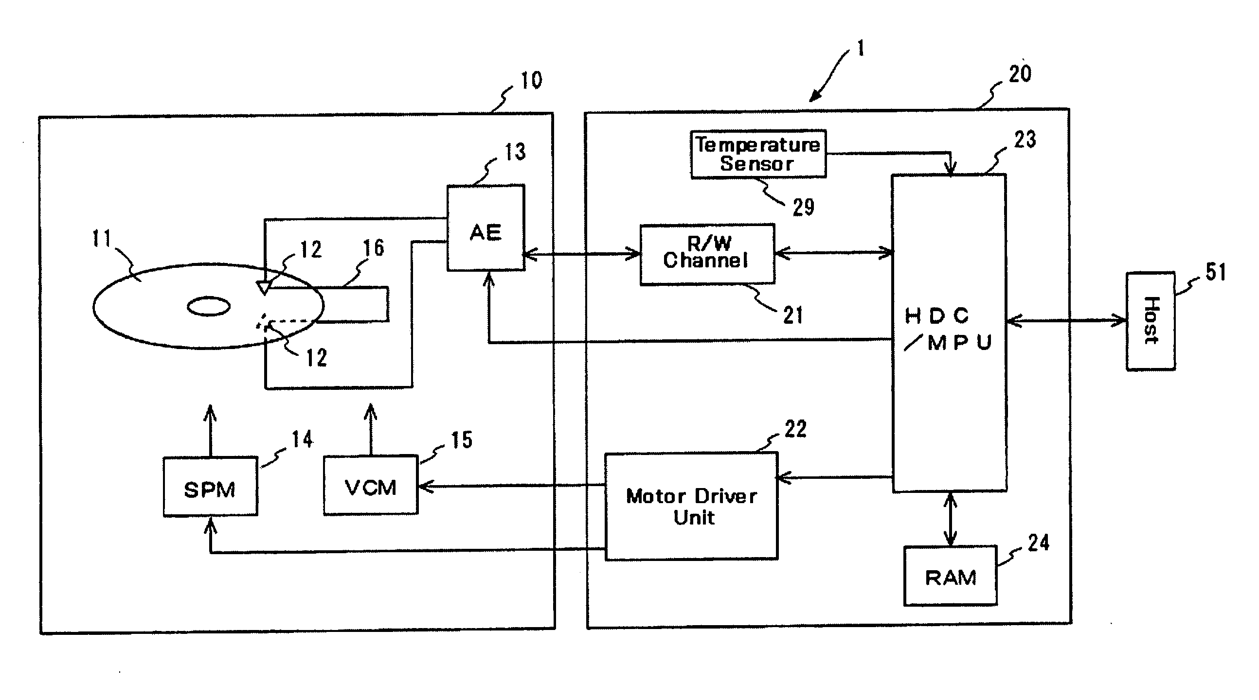
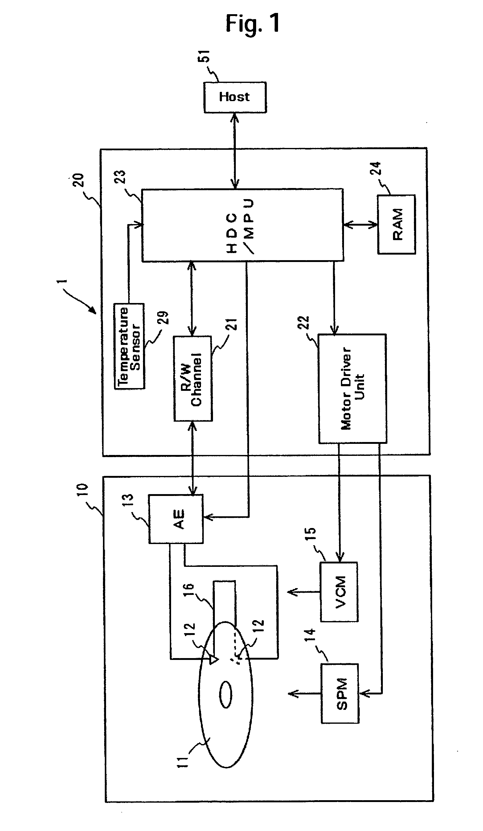
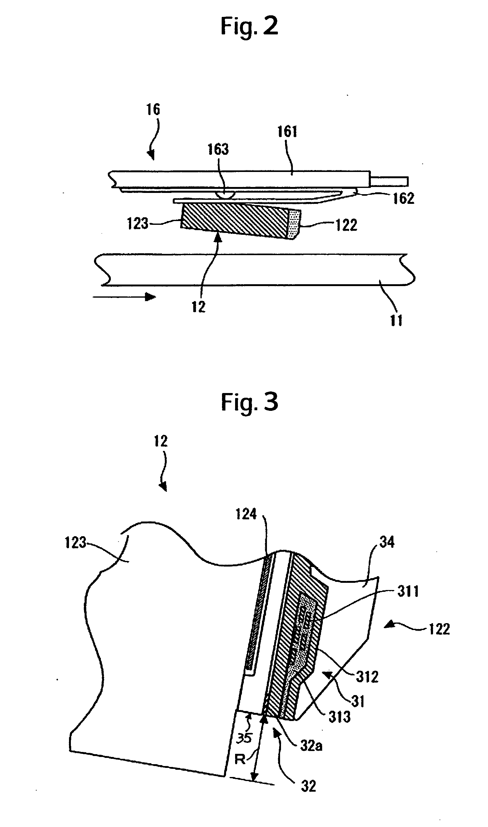
[0037] Using a hard disk drive (HDD) as an example of a magnetic storage apparatus embodiment, the following will provide a description of how the present invention is implemented. The characteristics of the present embodiment include write current control for the head element section of the HDD and heater power (heater current) control to adjust the clearance between the head element section and the magnetic disk. In the present embodiment, the recession of the head element section relative to the slider is measured and the write current or heater power to be given is determined according to the measured recession. This...


PUM


Abstract

Embodiments of the invention suppress collision between a head element section and a magnetic disk. In manufacturing a hard disk drive (HDD) according to an embodiment of the present invention, recession R is preliminarily measured for each head slider. Recession R means the amount of recession of the head element section relative to the slider. Write current and heater current values respectively for the write device and the TFC heater are registered based on the measured recession. Since these values are set according to the recession of the head element section, it is possible to prevent each head element section from colliding with the magnetic disk while reducing the clearance between each head element section and the magnetic disk.

Description

CROSS-REFERENCES TO RELATED APPLICATIONS [0001] This application claims priority from Japanese Patent Application No. JP2005-276410, filed Sep. 22, 2005, the entire disclosure of which is incorporated herein by reference. BACKGROUND OF THE INVENTION [0002] The present invention relates to a data storage apparatus and a manufacturing method thereof. In particular, the invention relates to a mechanism which controls the protrusion of a head element section in a data storage apparatus and a manufacturing technique which facilitates the control. [0003] As known, there are a variety of data storage devices which use different types of media such as optical disks and magnetic tapes. Among them, the hard disk drive (HDD) has become so popular as to be one of the indispensable storage devices for today's computer systems. Further, not limited to computers, the hard disk drive is widening its range of application more and more due to the superior characteristics, covering moving picture reco...

Claims


Application Information

Patent Timeline
IPC IPC(8): G11B21/02
CPCG11B5/6005
Inventor HIGASHIYA, TERUYOSHI
Owner WESTERN DIGITAL TECH INC
Why Eureka
Try Eureka