Plasma display panel and method of driving plasma display panel

a technology of plasma display panel and display panel, which is applied in the direction of electrode disposition, instruments, electric discharge tubes, etc., can solve the disadvantage of narrow width of the address electrode b>22/b>, and achieve the effect of preventing the reduction of light transmittan

Inactive Publication Date: 2007-03-22
SAMSUNG SDI CO LTD
View PDF2 Cites 0 Cited by
  • Summary
  • Abstract
  • Description
  • Claims
  • Application Information

AI Technical Summary

Benefits of technology

[0013] An aspect of the invention provides a plasma display panel having an address electrode structure that has a large crossing portion between an address electrode and a sustain electrode and prevents the reduction of light transmittance despite the address electrode being located on a front substrate through which the light is transmitted.

Problems solved by technology

Therefore, the narrow width of the address electrodes 22 is a disadvantage in this regard.

Method used


Image

  • Plasma display panel and method of driving plasma display panel
  • Plasma display panel and method of driving plasma display panel
  • Plasma display panel and method of driving plasma display panel

Examples


Embodiment Construction

[0034] Reference will now be made in detail to embodiments of the invention, examples of which are shown in the accompanying drawings, wherein like reference numerals refer to like elements throughout. The embodiments are described below in order to explain the invention by referring to the figures.

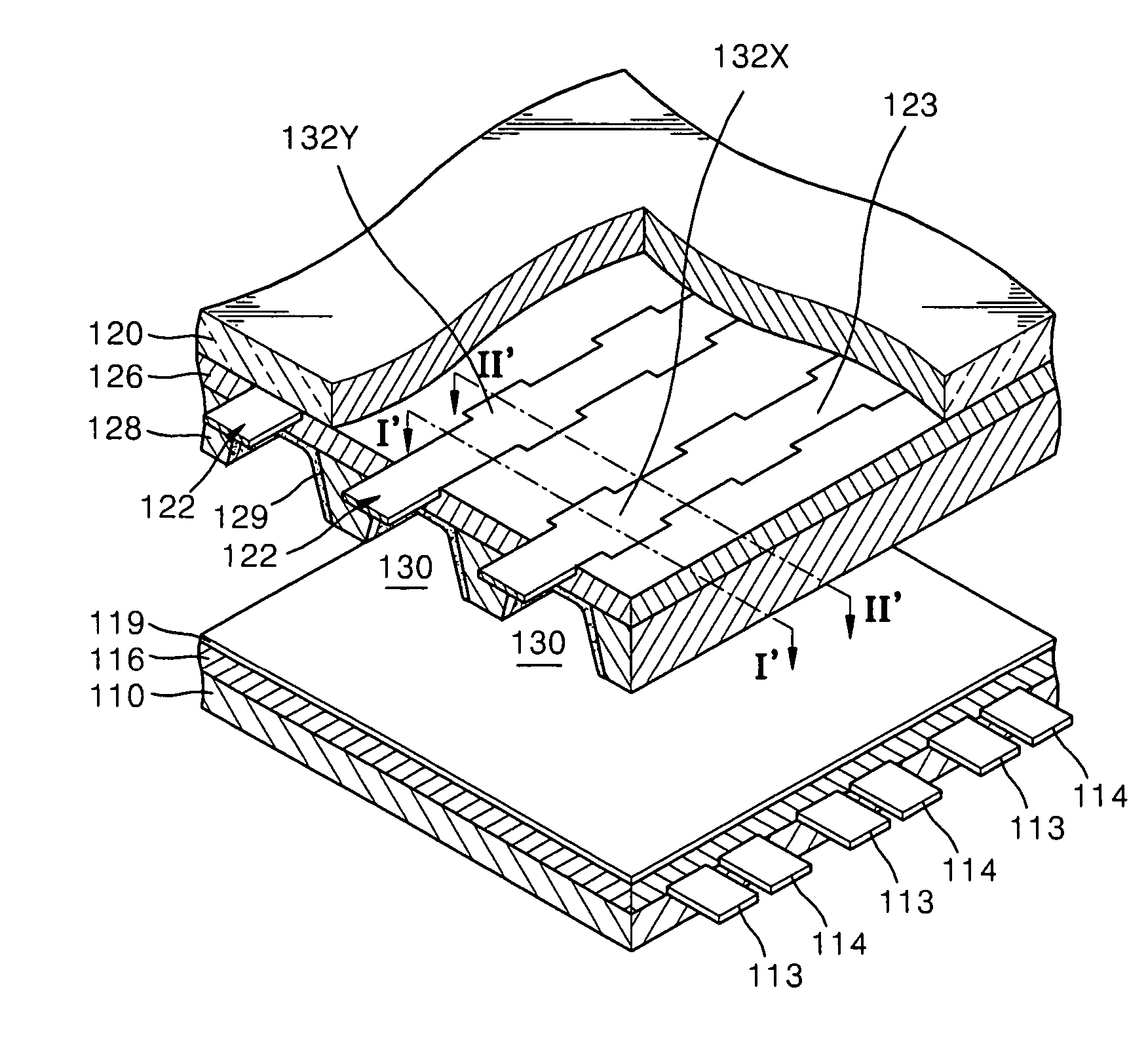
[0035]FIG. 4 is a partially cutaway exploded perspective view of a plasma display panel according to an embodiment of the invention, FIG. 5 is an exploded perspective view showing the relationship of electrodes of the plasma display panel of FIG. 4 according to an embodiment of the invention, and FIG. 6 is a plan view illustrating the relationship of electrodes of the plasma display panel of FIG. 4 according to an embodiment of the invention.

[0036] Referring to FIG. 4, the plasma display panel according to an embodiment of the invention includes a rear substrate 110; a plurality of sustain electrode pairs 113 and 114 formed on the rear substrate 110, each sustain electrode pair 113 and ...


PUM


Abstract

A plasma display panel includes a plurality of sustain electrode pairs, each of the sustain electrode pairs including an X electrode and a Y electrode; and a plurality of address electrodes crossing the sustain electrode pairs; wherein each of the address electrodes includes a main section having a first width, and extended-width portions having a second width greater than the first width, the extended-width portions being formed where the address electrode crosses either the X electrodes or the Y electrodes of the sustain electrode pairs.

Description

CROSS-REFERENCE TO RELATED APPLICATION [0001] This application claims the benefit of Korean Application No. 2005-40552 filed on May 16, 2005 in the Korean Intellectual Property Office, the disclosure of which is incorporated herein by reference in its entirety. BACKGROUND OF THE INVENTION [0002] 1. Field of the Invention [0003] An aspect of the invention relates to a plasma display panel, and more particularly to a plasma display panel that can reduce a capacitance between adjacent address electrodes and can increase transmission of light by alternately arranging the address electrodes. [0004] 2. Description of the Related Art [0005] Due to their characteristics of high brightness and a large viewing angle, the use of plasma display panels that display images using an electric discharge has been rapidly increasing. A plasma display panel emits visible light when a phosphor material is excited by ultraviolet rays generated by gas discharge which occurs between electrodes when a direc...

Claims


Application Information

Patent Timeline
Patent Type & Authority Applications(United States)
IPC IPC(8): G09G3/28
CPCH01J11/12H01J11/26H01J2211/323H01J2211/265H01J11/32
Inventor SON, SEUNG-HYUNKIM, YOUNG-MOHATANAKA, HIDEKAZUJANG, SANG-HUNLEE, HO-NYEON
Owner SAMSUNG SDI CO LTD
Why Eureka
Try Eureka