
Folding top assembly with adjustable roof bow

a technology for folding tops and roof bows, which is applied to roofs, vehicle components, engine seals, etc., can solve the problems of increasing the space required perpendicular to the transverse axis of the roof bow, consuming a relatively large amount of storage space, and reducing the amount of space required, so as to achieve the effect of strengthening the roof bow

Inactive Publication Date: 2007-03-22
MAGNA CAR TOP SYST GMBH +1
View PDF12 Cites 15 Cited by
  • Summary
  • Abstract
  • Description
  • Claims
  • Application Information

AI Technical Summary

Benefits of technology

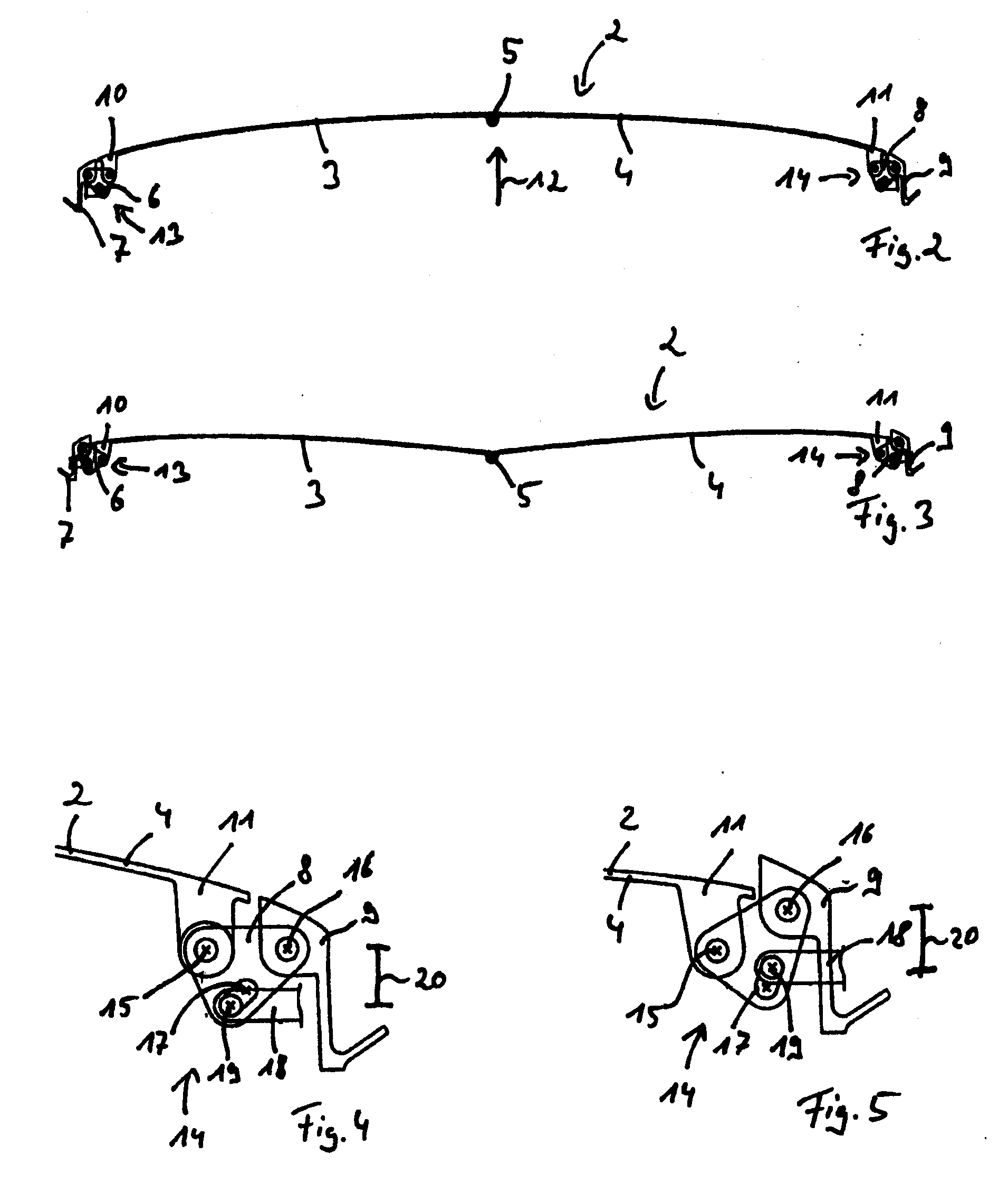
[0011] In an embodiment of the present invention, at least one adjusting device is used to change the direction of arching of the roof bow. In this embodiment, the arching direction of the roof bow is different in the closed position than in the stored position. The change in the arching direction of the roof bow changes its shape. This allows the roof bow to be adapted to the shape of the rest of the folding top in the stored position and / or to the shape of a storage compartment for the folding top. This results in saving space occupied by the entire folding top in the stored position.
[0032] In an embodiment of the present invention, the roof bow is made as a single piece out of an elastic material. In this case, it is possible to do without intermediate joints. If the entire roof bow is made out of an elastic material, it is necessary to see to it that it is sufficiently strong. In the closed position, the strength of the roof bow can be ensured by laying the roof bow on supports on the vehicle body.

Problems solved by technology

A problem is that the roof bow consumes a relatively large amount of storage space when the folding top is in its stored position.
Although this reduces the amount of space required in the transverse direction, it increases the space required perpendicular to the transverse axis of the roof bow.

Method used


Image

  • Folding top assembly with adjustable roof bow
  • Folding top assembly with adjustable roof bow
  • Folding top assembly with adjustable roof bow

Examples


Embodiment Construction

)

[0045] In the figures, components that are the same and components that have the same function are labeled with the same reference numbers.

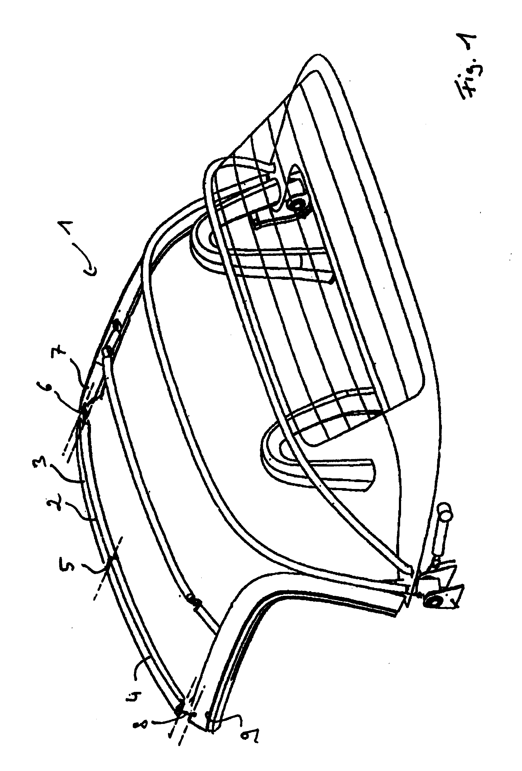
[0046] Referring now to FIG. 1, a perspective view of a folding top 1 in accordance with an embodiment of the present invention is shown. Folding top 1 is for use with a motor vehicle. Folding top 1 is movable between a closed position in which the folding top covers the vehicle interior and a stored (stowed or opened) position in which the folding top is stored in a storage area of the vehicle thereby exposing the vehicle interior. As such, folding top 1 is extended in the closed position and is compressed together in the stored position.

[0047] Folding top 1 includes at least one slightly arched roof bow such as roof bow 2. Each roof bow runs transversely to the vehicle's longitudinal axis. As shown in FIG. 1, roof bow 2 is arranged in the front area of folding top 1. Alternatively, roof bow 2 may be arranged in the middle or rear areas of th...


PUM


Abstract

A motor vehicle folding top assembly includes a folding top movable between a closed position in which the folding top is extended along a longitudinal axis and a stored position in which the folding top is compressed. An arched roof bow is connected to the folding top and runs transversely to the longitudinal axis. An adjusting device is connected to the first roof bow and is pivotably connected to the folding top such that upon actuation, while the folding top moves between the closed and stored positions, the adjusting device pivots to move the roof bow and thereby change the degree or direction of arching of the roof bow such that the arching degree in the stored position is less than the arching degree in the closed position or the direction of arching in the stored position is different than the direction of arching in the closed position.

Description

CROSS-REFERENCE TO RELATED APPLICATIONS [0001] This application claims foreign priority benefits under 35 U.S.C. § 119(a)-(d) to DE 10 2005 044 742.2, filed Sep. 19, 2005, which is hereby incorporated by reference in its entirety. BACKGROUND OF THE INVENTION [0002] 1. Field of the Invention [0003] The present invention relates to a motor vehicle folding top movable between closed and stored positions and having an arched roof bow running transverse to the vehicle's longitudinal axis with the roof bow arranged in the area of the folding top adjacent to the vehicle body when the folding top is in the closed position such that the roof bow may lock to a windshield frame of the motor vehicle. [0004] 2. Background Art [0005] DE 197 34 671 C2 (corresponds to U.S. Pat. No. 5,938,271) describes a folding top having a slightly arched and rigid roof bow. The roof bow may lock with the windshield frame of a vehicle body when the folding top is in its closed position. A problem is that the roof...

Claims


Application Information

Patent Timeline
IPC IPC(8): B60J7/12
CPCB60J7/1204
Inventor ZEHNDER, FRANKHALBWEISS, THOMAS
Owner MAGNA CAR TOP SYST GMBH
Learn More