Methods and devices for mapping the ventricle for pacing lead placement and therapy delivery
a technology of ventricle and pacing leads, applied in the field of biventricular pacing, can solve problems such as optimal placement, and achieve the effects of optimizing heart function, improving placement of pacing leads, and measuring the effectiveness of pacing from the location
- Summary
- Abstract
- Description
- Claims
- Application Information
AI Technical Summary
Benefits of technology
Problems solved by technology
Method used
Image
Examples
first embodiment
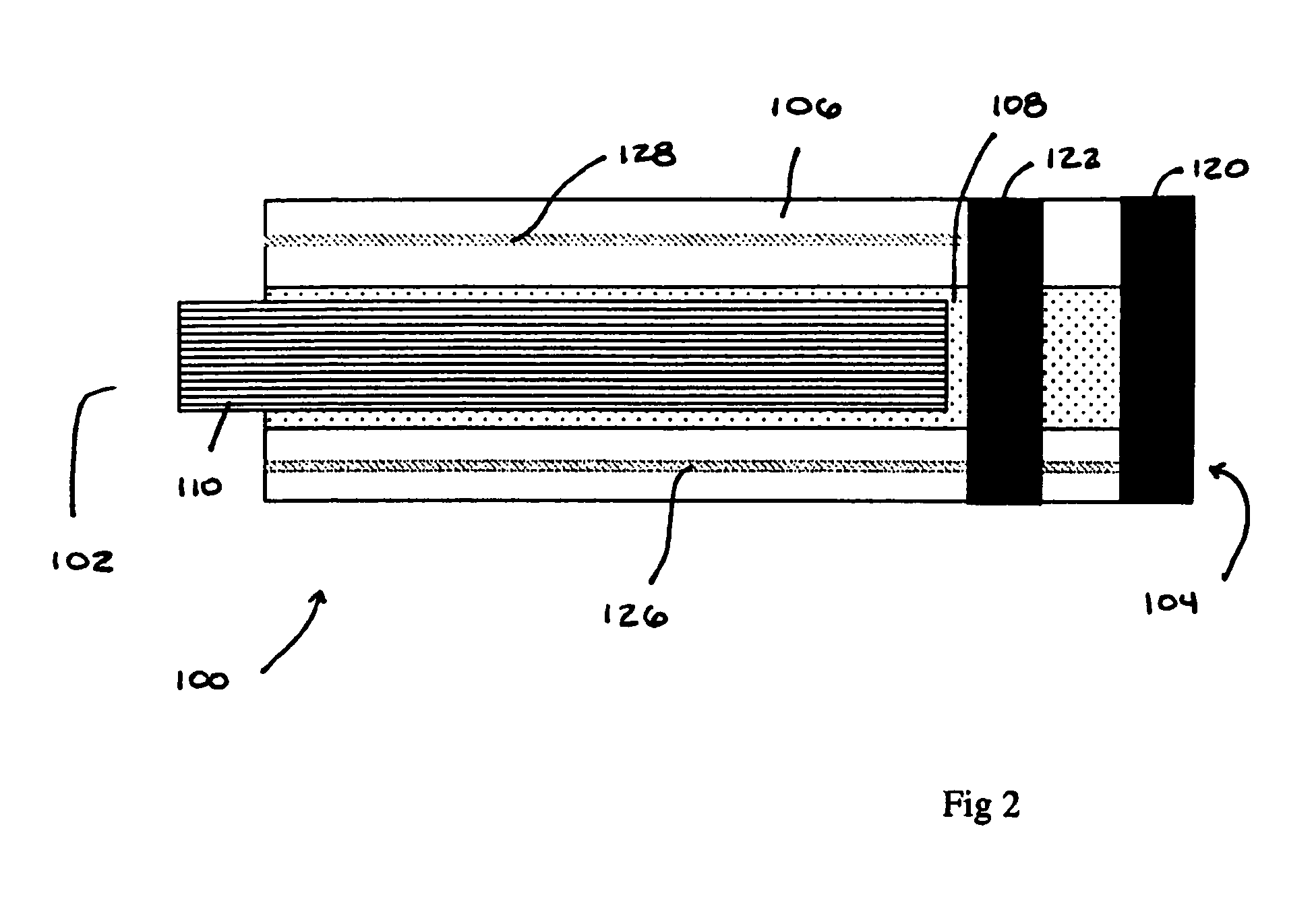
[0032] a device useful in at least some of the preferred embodiments of the methods of this invention is indicated generally as 100 in FIG. 2. The device 100 has a proximal end 102, a distal end 104, and a sidewall 106 forming lumen 108 extending therebetween. In the preferred embodiment the lumen 108 is adapted to receive and pass a guide wire 110 for facilitating the navigation of the device 100. There are preferably two ring electrodes 120 and 122 on the distal end of 104 of the device. The electrodes 120 and 122 may be positioned at the distal end of the device 100. The electrode 122 is positioned proximal to, and spaced from, the electrode 120. Conductors 126 and 128 extend from the electrodes 120 and 122, respectively through the wall 106 of the device 100 to the proximal end where they can be connected to suitable equipment for sensing signals between the electrodes 120 and 122 and for applying a pacing signal between the electrodes 120 and 122.
[0033] The guide wire 110 can b...
second embodiment
[0034] a device useful in at least some of the preferred embodiments of the methods this invention is indicated generally as 150 in FIG. 3. The device 150 has a proximal end 152, a distal end 154, and a sidewall 156 forming lumen 158 extending therebetween. In the preferred embodiment the lumen 158 is adapted to receive and pass a guide wire 160 for facilitating the navigation of the device 150. The guide wire 160 can have one or more magnetically responsive elements 162 thereon. These elements 162 can be made from a permanent magnetic material or a permeable magnetic material of sufficient size and shape that it tends to align the distal end of the guide wire 160 relative to an externally applied magnetic field. There are preferably two ring electrodes 170 and 172 on the distal end of 154 of the device 150. The electrode 170 may be positioned at the distal end of the device 150. The electrode 172 is positioned proximal to, and spaced from, the electrode 170. Conductors 176 and 178 ...
third embodiment
[0036] a device useful in at least some of the preferred embodiments of the methods this invention is indicated generally as 200 in FIGS. 4 and 5. The device 200 has a proximal end 202, a distal end 204, and a sidewall 206 forming lumen 208 extending from the proximal end to a point proximal to the distal end 204. In the preferred embodiment the lumen 208 is adapted to receive a guide wire 210 for facilitating the navigation of the device 200, the guide wire 210 can function to engage and push the distal end of the device 200. In addition, or alternatively, the guide wire 210 may function to stiffen at least the distal portion of the device 200. The guide wire 210 can optionally have one or more magnetically responsive elements (not shown) thereon. These elements can be made from a permanent magnetic material or a permeable magnetic material of sufficient size and shape that it tends to align the distal end of the guide wire 210 relative to an externally applied magnetic field. Thus...
PUM
 Abstract
Description
Claims
Application Information
 - R&D
- Intellectual Property
- Life Sciences
- Materials
- Tech Scout
- Unparalleled Data Quality
- Higher Quality Content
- 60% Fewer Hallucinations
Browse by: Latest US Patents, China's latest patents, Technical Efficacy Thesaurus, Application Domain, Technology Topic, Popular Technical Reports.
© 2025 PatSnap. All rights reserved.Legal|Privacy policy|Modern Slavery Act Transparency Statement|Sitemap|About US| Contact US: help@patsnap.com


