
Sliding shell

Inactive Publication Date: 2007-03-15
GIGA BYTE COMM INC +1
View PDF24 Cites 1 Cited by
  • Summary
  • Abstract
  • Description
  • Claims
  • Application Information

AI Technical Summary

Benefits of technology

[0005] The primary objective of the present invention is to provide a sliding shell with a smooth sliding and more abrasion durability. The structure of the sliding shell comprises a first shell body having a first surface, a first interface layer formed by coating a smooth material on the first surface, a first sliding assembly formed on the first surface of the first shell body, a second shell body having a second surface, and a second sliding assembly formed on the second surface of the second shell body and connected with the first sliding assembly correspondingly to allow the first shell body sliding between the first position and the second position on the second shell body. In addition, the first interface layer overlaps the second surface when the first and second shell bodies are connected as a relatively sliding status via the first and second sliding assemblies.

Problems solved by technology

Thus, there will be a certain level of friction force generated between the two plastic shells during sliding that would not only cause the sliding of the two plastic shells not smoothly, but also be liable to leave the abrasive marks on the surfaces of the two plastic shells that affects the appearance of the mobile phone.
However, even the above-mentioned method can reduce the friction resistance, it will still exists with the abrasive marks.
While improving the flatness of surfaces between two shells, both of the unfavorable products and the cost of the products will increase accordingly.
However, the two methods will both increase the gap between two plastic shells to affect the appearance impression.
Furthermore, the protection sheet applied to the second method increases the friction resistance to cause the sliding of two plastic shells further not smoothly.

Method used


Image

  • Sliding shell
  • Sliding shell
  • Sliding shell

Examples


Embodiment Construction

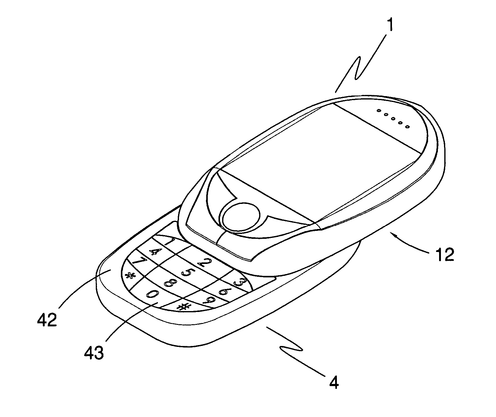
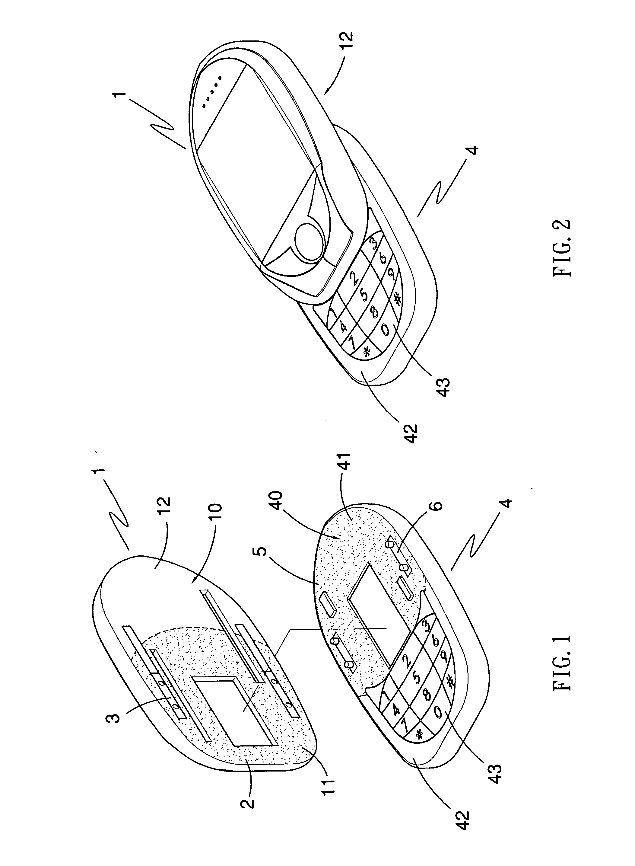
[0013]FIG. 1 shows a first preferred embodiment of the present invention, which is a sliding shell applied on slide-type mobile phone and the sliding shell comprises a first shell body 1, a first interface layer 2, a first sliding assembly 3, a second shell body 4, a second interface layer 5, and a second sliding assembly 6.

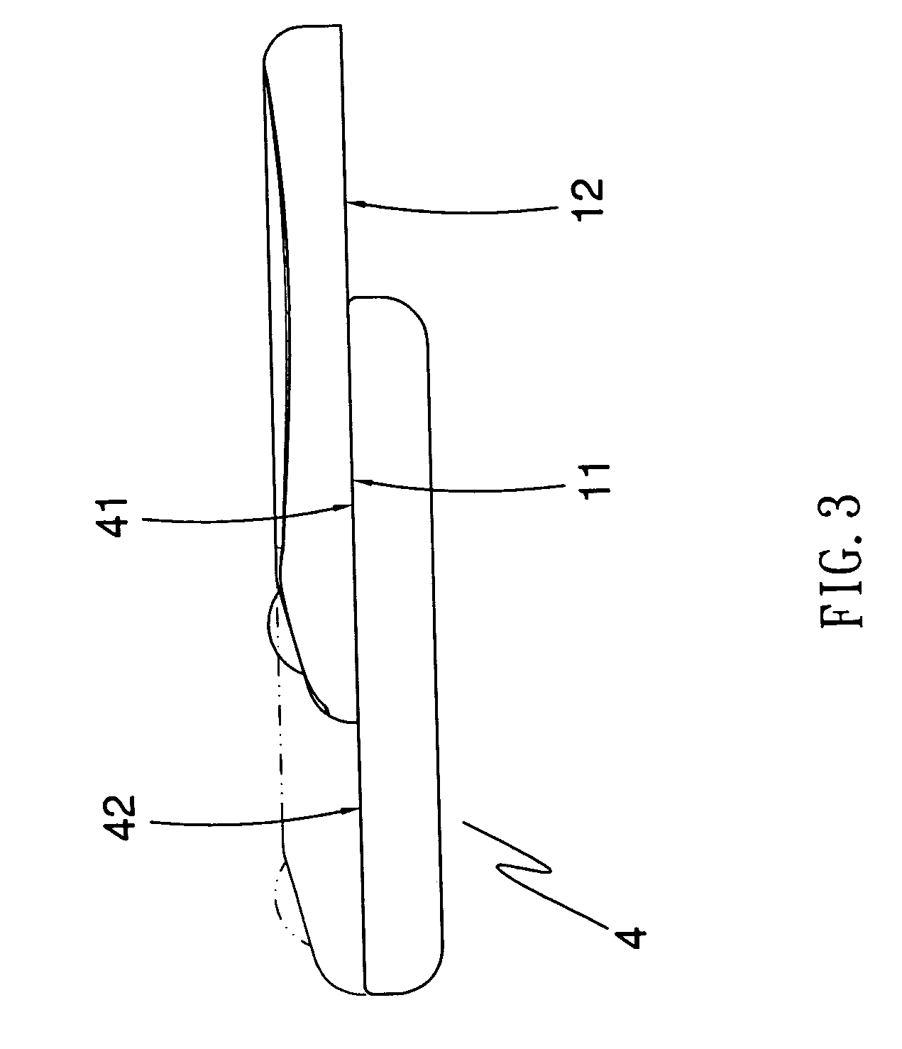
[0014] The first shell body 1 has a first surface 10, which has a connecting area 11 and a protrusive area 12 thereon. Furthermore, the first interface layer 2 is formed by coating a smooth material on the connecting area 11 of the first surface 10, and the smooth material is a Teflon material. In addition, the first sliding assembly 3 is formed on the first surface 10 of the first shell body 1. The second shell body 4 has a second surface 40, which has a supporting area 41 and an exposed area 42 thereon, and the exposed area 42 has a plurality of buttons (43) thereon.

[0015] Moreover, the second interface layer 5 is formed by coating a smooth material on the su...


PUM


Abstract

A sliding shell comprises a first shell body with a first surface, a first interface layer formed by coating a smooth material on the first surface, a first sliding assembly formed on the first surface of the first shell body, a second shell body with a second surface, and a second sliding assembly formed on the second surface of the second shell body. The second sliding. assembly is correspondingly connected to the first sliding assembly to allow the first shell body sliding between the first position and the second position on the second shell body. In addition, the first interface layer overlaps the second surface, and thus the first interface layer can make the sliding between two shell bodies with benefits of smooth sliding and abrasion prevention.

Description

TECHNICAL FIELD [0001] This invention relates generally to a technology for a sliding shell on a slide-type mobile phone, and particularly to a sliding shell with a smooth slide and abrasion durability. BACKGROUND OF THE INVENTION [0002] A conventional sliding shell on a slide-type mobile phone is usually composed of two plastic shells. The two plastic shells are combined by a set of guideway mechanism for being capable to slide relatively. The opposite combined surfaces of the two plastic shells are directly overlapped and contacted according to the requirement of appearance and quality of the mobile phone. Thus, there will be a certain level of friction force generated between the two plastic shells during sliding that would not only cause the sliding of the two plastic shells not smoothly, but also be liable to leave the abrasive marks on the surfaces of the two plastic shells that affects the appearance of the mobile phone. [0003] Currently, the method for solving the large fric...

Claims


Application Information

Patent Timeline
IPC IPC(8): H04M1/00
CPCH04M1/0235
Inventor LIN, HUNG-CHIHCHENG, SHUN-FAN
Owner GIGA BYTE COMM INC
Learn More