
Self illuminating belt buckle

a belt buckle and self-illuminating technology, applied in the field of belt buckles, can solve the problems of not being able to illustrate any of these patents, and achieve the effect of being ready to be used

Inactive Publication Date: 2007-03-15
SEVILLA FREDERICK J
View PDF19 Cites 51 Cited by
  • Summary
  • Abstract
  • Description
  • Claims
  • Application Information

AI Technical Summary

Benefits of technology

[0009] The present invention may be readily adapted for use with a wide variety of fashion accessories. Embodiments of the present invention may provide, among other benefits: an accessory with a backlit symbol or insignia which has a self contained power source.
[0010] The present invention consists of a housing containing a power source which is workably coupled to at least one light source. The housing having a symbol or insignia cut into it and the light source producing back lighting for the symbol. The housing may be connected to a buckle or other accessory attachment device which allows the user to use the housing as a belt buckle or other accessory. The housing may also have an opening in the bottom which allows the light source to shine through providing an effect similar to that produced when neon lights are attached to the undercarriage of a car.

Problems solved by technology

None of these patents, however, illustrate a self illuminating belt buckle or insignia in which the light is placed behind an insignia in order to provide a background glow.

Method used


Image

  • Self illuminating belt buckle
  • Self illuminating belt buckle
  • Self illuminating belt buckle

Examples


Embodiment Construction

[0019] As discussed above, embodiments of the present invention relate to a self illuminating belt buckle or accessory.

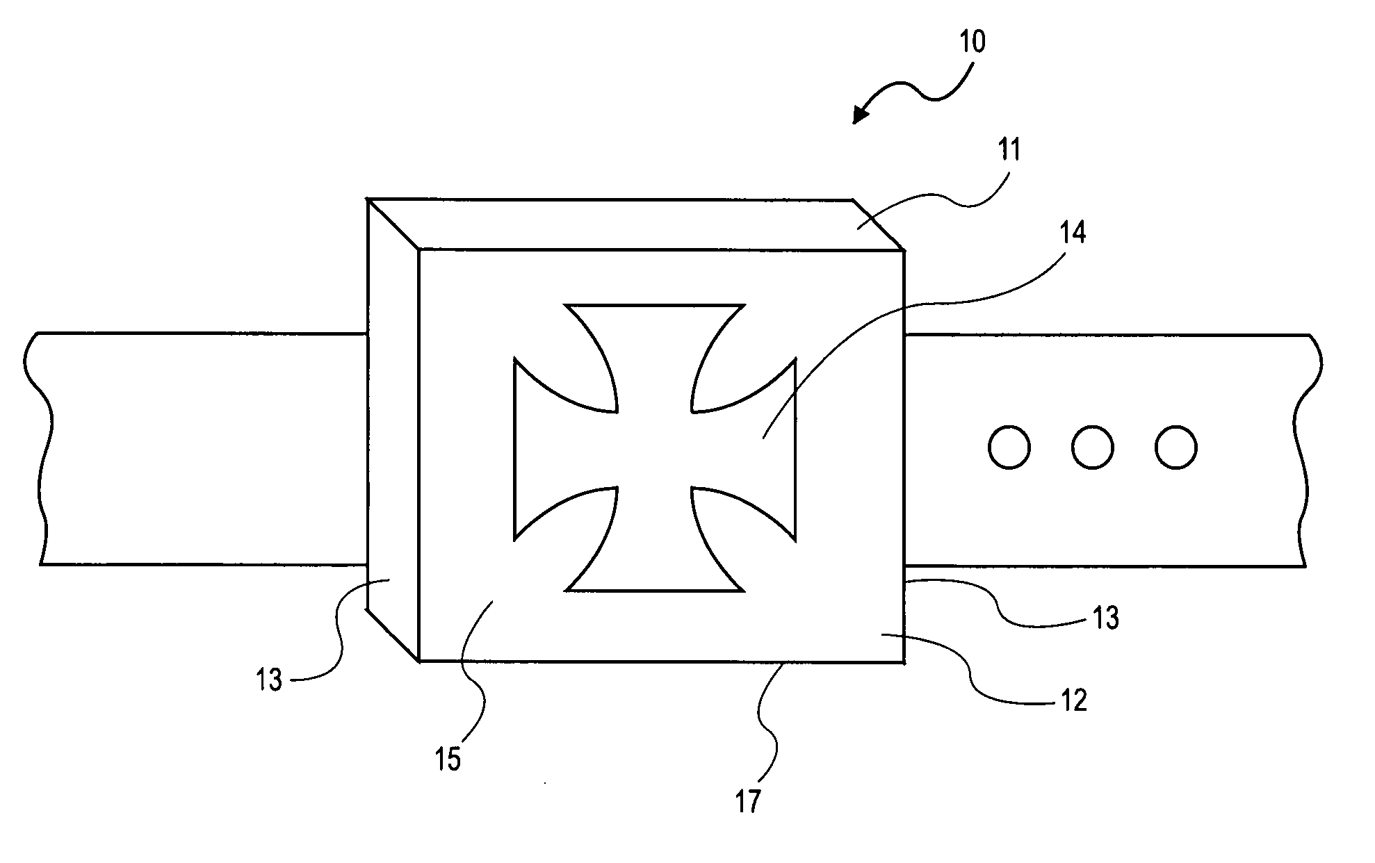
[0020]FIG. 1 illustrates a self illuminating belt buckle configured according to an embodiment of the present invention. The self illuminating belt buckle 10 comprises a housing 12. The housing 12 may consist of a top 11, bottom 17, front 15, back 19 (as seen in FIGS. 5 and 6) and two side pieces 13. Though several of these pieces may be formed from a single section of material. The pieces of the housing 12 may be connected in any way that provides the desired effect and the strength required for a self illuminating belt buckle 10, such as welding or the like. The bottom piece of the housing may have an opening 18 in it as shown in FIG. 3.

[0021] As shown in FIG. 1, the front of the housing may have an opening formed in the shape of a symbol or insignia 14. Preferable symbols or insignia 14 include common trademarks or other symbols associated with pop culture. It ...


PUM


Abstract

A self illuminated belt buckle comprising a housing with a symbol shaped opening in the front and an opening in the bottom of the housing. The housing containing at least one power source, and at least one light source such as an LED which may be connected to a switch. The at least one power source providing power to the light source which provides background lighting through the symbol shaped opening and through the opening in the bottom of the housing. The light source and power source not being visible from outside of the housing. The housing further being connected to an attachment device such as a belt buckle or brooch pin. The housing also being formed from diamond plate.

Description

BACKGROUND OF THE INVENTION [0001] 1. Technical Field [0002] This invention relates to a belt buckle which has an illuminated symbol and an opening which creates a similar effect to that produced by neon lights attached to the undercarriage of a car. [0003] 2. Background Art [0004] In many parts of the United States and abroad the latest fashion craze is anything bright, shiny and flashy. This has created a fashion trend that utilizes all of the latest high tech developments in order to create the most attention grabbing accessories. [0005] Examples of accessories which utilize technology and have previously been patented include Oberlander U.S. Pat. No. 5,193,896 (“Oberlander”). The Oberlander patent discloses a lighting device for personal use that is worn on the wrist like a watch and provides a light source. Zoller et al. U.S. Pat. No. 6,805,460 discloses a flashlight which is attached to a dog's collar. The dog collar of Zoller shines light on the path in front of and surroundi...

Claims


Application Information

Patent Timeline
IPC IPC(8): F21V21/08
CPCA44B11/001F21V33/0008A44C15/0015Y10S362/806
Inventor SEVILLA, FREDERICK J. II
Owner SEVILLA FREDERICK J
Learn More