
Optical storage device decoding method

a decoding method and optical storage technology, applied in the field of decoding methods, can solve the problems of not being able to reduce the overall data error rate of the optical disc system, and achieve the effect of improving the reliability of channel bits

Inactive Publication Date: 2007-03-15
LITE ON IT
View PDF2 Cites 0 Cited by
  • Summary
  • Abstract
  • Description
  • Claims
  • Application Information

AI Technical Summary

Benefits of technology

[0008] An object of the present invention is to provide a decoding method of channel bits upon optical storage systems that improves the reliability of channel bits by adjusting the RF value of receiving optical signals.
[0009] Another object of the present invention is to provide a decoding method of optical storage systems that reduces the error rate of the optical storage system by reducing the error rate of channel bits.

Problems solved by technology

The error control / correction code is not good enough to reduce the overall data error rate of the optical disc system; especially the current trend is towards increasing the storage density of the discs.

Method used


Image

  • Optical storage device decoding method
  • Optical storage device decoding method
  • Optical storage device decoding method

Examples


Embodiment Construction

[0018] The following detailed description of the present invention describes the optical storage device decoding method necessary to provide an understanding of the present invention, but does not cover a complete structure composition and the operating theory. The portions relating to the conventional techniques are briefly described, and the parts of the drawings are not proportionally drafted. While embodiments are discussed, it is not intended to limit the scope of the present invention. Except expressly restricting the amount of the components, it is appreciated that the quantity of the disclosed components may be greater than that disclosed.

[0019] Upon an optical storage disc, a transition from land to pit or from pit to land represents a “1”, and all other areas represent a “0”. According to the prior art, the number of “0”s between two “1”s is limited to between n at most and m at least by the RLL(m,n). In other words, corresponding to the pits and lands upon an optical sto...


PUM


Abstract

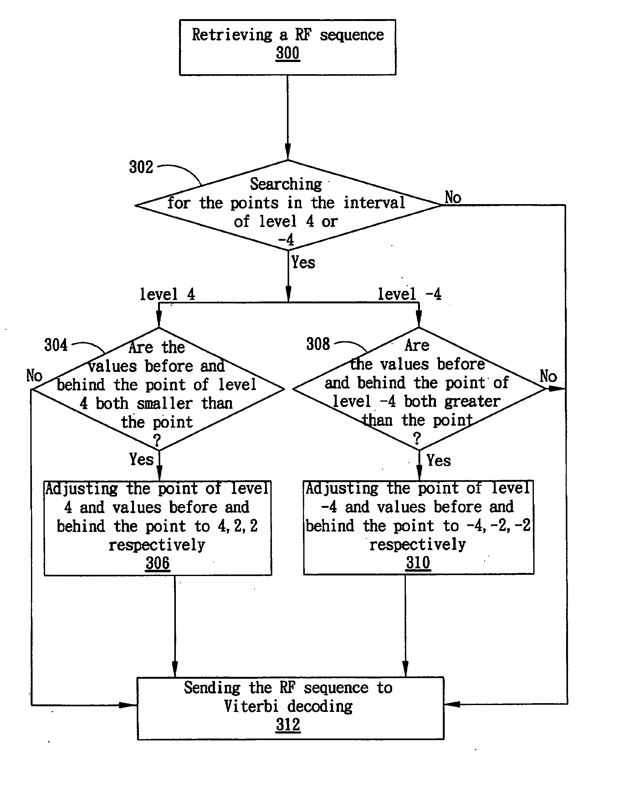
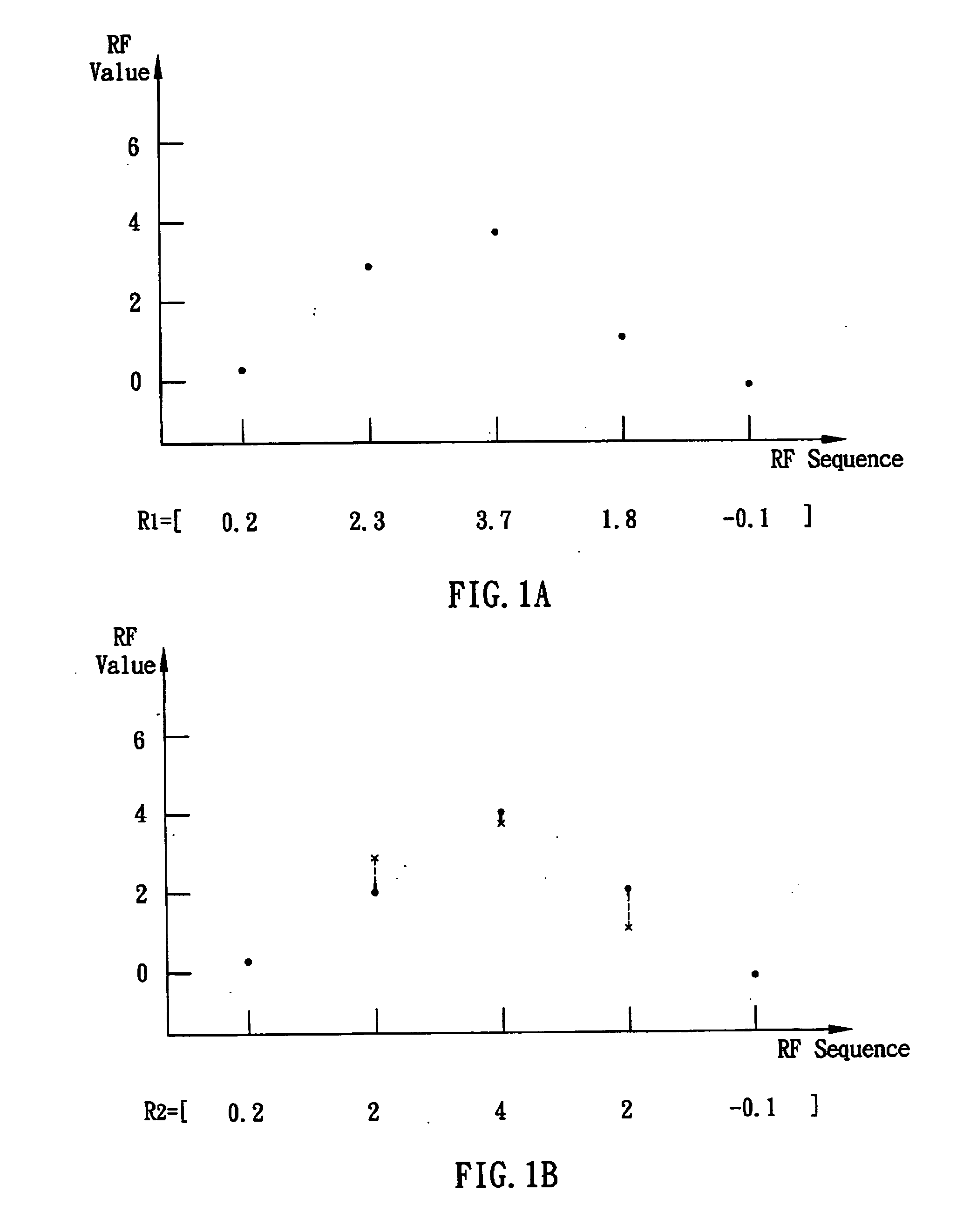
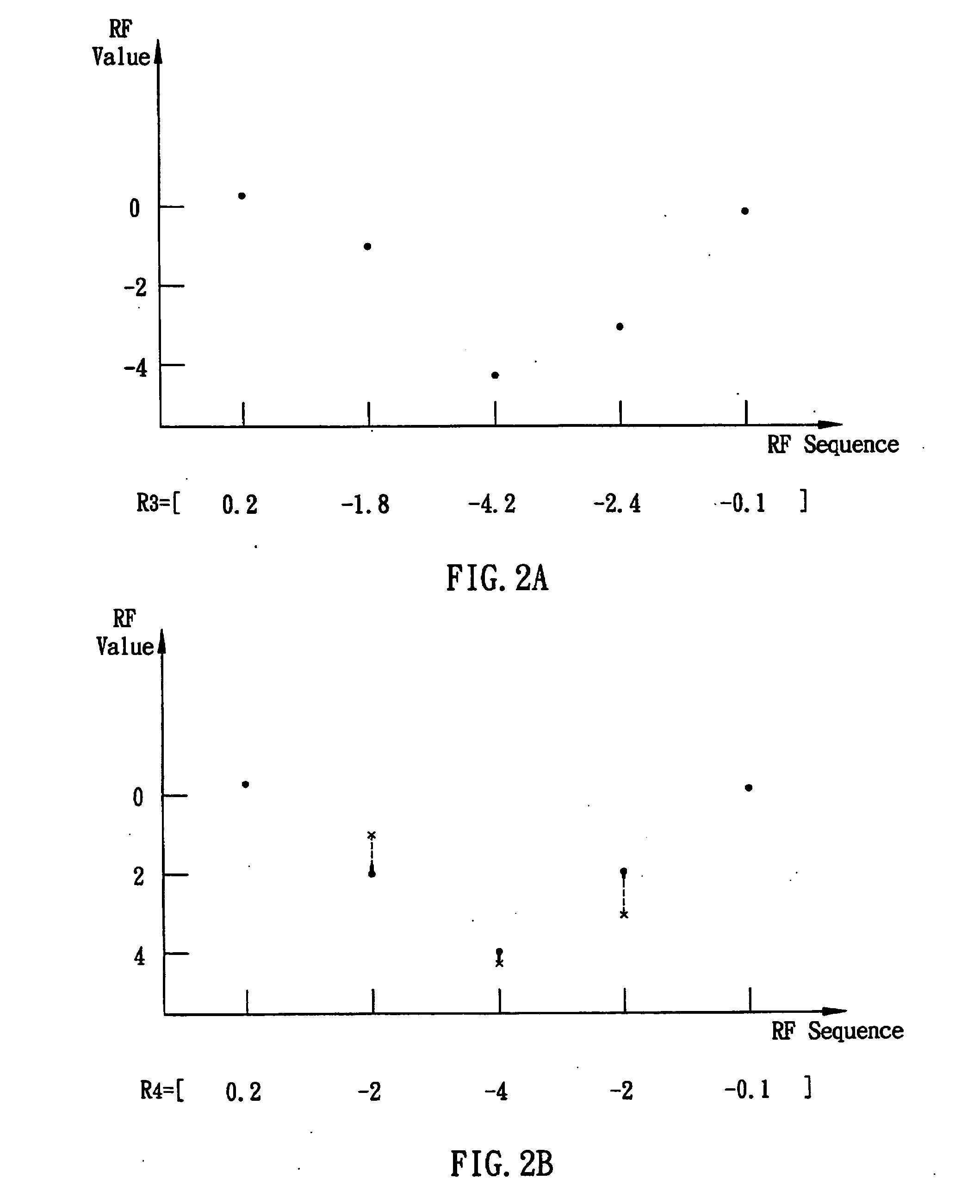
A decoding method for optical storage device, which decodes channel bits upon a disc by partial response maximum likelihood (PRML) detection, is proposed. Unlike the conventional skills, the present method does not decode the detected RF signals directly, but adjusts values of parts of detected RF signals to their original ideal values before channel decoding instead, thereby reducing the decoding error rate of channel bits. The decoding method includes the step of: retrieving a first sequence of RF signals; identifying if the first sequence of RF signals contains a signal combination which satisfies a particular condition; adjusting a plurality of RF signals in the first sequence of RF signals to some pre-determined RF signals' value and then forming a second sequence of RF signals; and decoding the second sequence of RF signals. In a preferred embodiment of the invention, the method is applied to an optical storage system of PR (1,2,2,2,1) channel.

Description

BACKGROUND OF THE INVENTION [0001] 1. Field of the Invention [0002] The present invention relates to a decoding method, and more particularly relates to a decoding method of an optical storage system that reduces the decoding error rate of channel bits by adjusting radio frequency (RF) values of the optical signal. [0003] 2. Description of the Prior Art [0004] Encoding method is a very important part of the digital systems, especially the digital communication systems and data storage systems. Generally there are three types of encoding methods: source coding, error control coding, and channel coding. The object of source coding is to transform the information from human or computer to the sequence of digital data, especially binary sequence, and compress contents of the information. The object of error control coding is to encode the sequence of digital data becoming a new sequence of bits with functions of error signal detection and correction. And the object of channel coding is ...

Claims


Application Information

Patent Timeline
Patent Type & Authority Applications(United States)
IPC IPC(8): H03M7/00
CPCG11B20/10009G11B20/10055G11B2020/1863G11B20/1426G11B20/1012
Inventor CHANG, CHIA-YEN
Owner LITE ON IT
Learn More