
Purge fuel vapor control

a technology of purging fuel and vapor, applied in the direction of condensed fuel collection/return, charge feed system, non-fuel substance addition to fuel, etc., can solve the problems of excessive air to fuel ratio, erroneous results, etc., and achieve the effect of limiting alignmen

Inactive Publication Date: 2007-03-15
FORD GLOBAL TECH LLC
View PDF8 Cites 3 Cited by
  • Summary
  • Abstract
  • Description
  • Claims
  • Application Information

AI Technical Summary

Benefits of technology

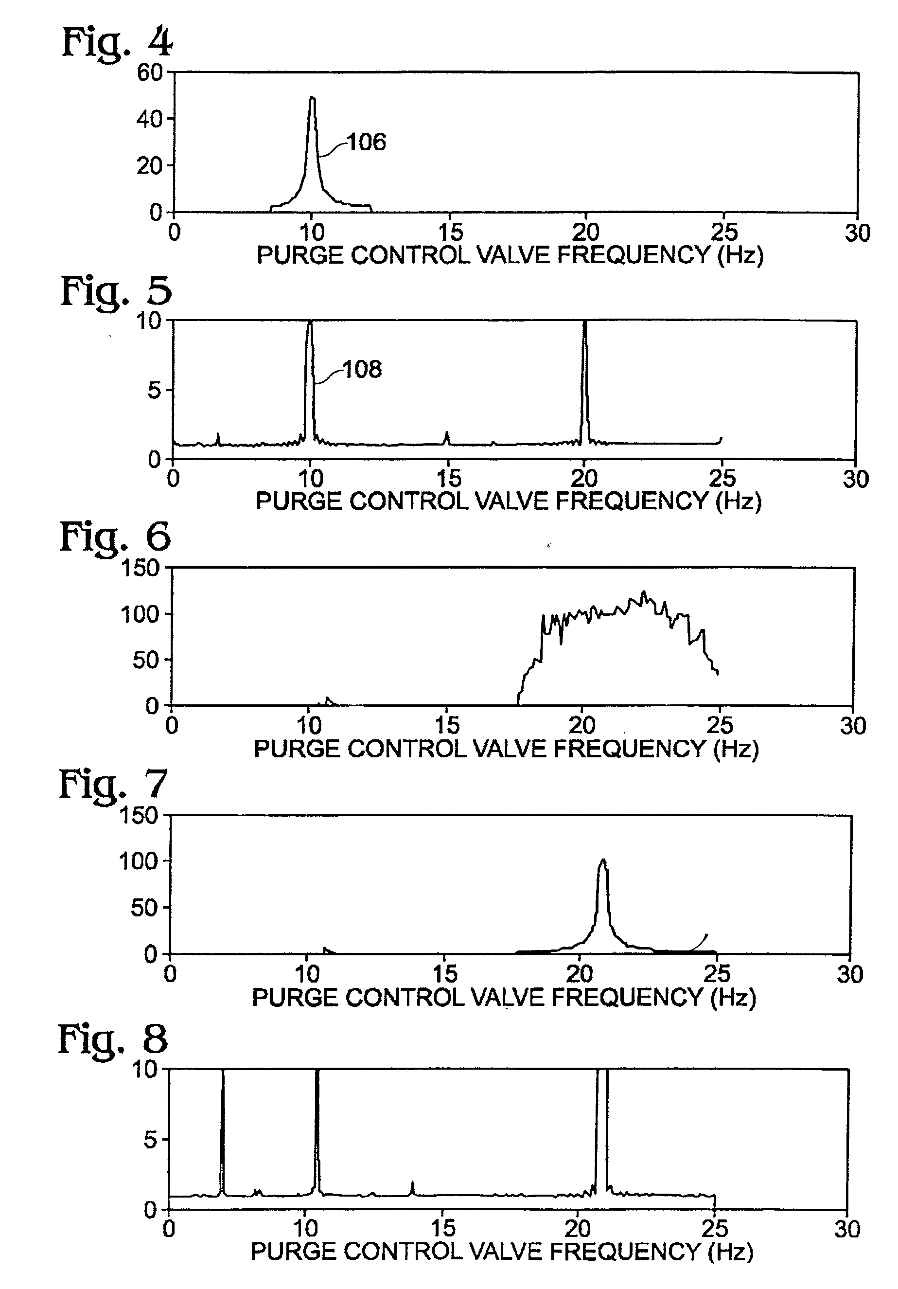
[0007] At least some of the above issues may be addressed by a system and method for changing purge valve on-pulse period (frequency) according to a predetermined schedule without monitoring engine speed, an elapsed time, or other real-time operating parameters of the engine. In this way, it may be possible to limit alignment between the on-pulse of a purge control valve and consecutive intake strokes of a particular cylinder without requiring synchronization with engine cylinder events, and / or real-time monitoring of engine speed, elapsed time, or other operating parameters of the engine.

Problems solved by technology

This is undesirable, because it can result in an excessively rich air to fuel ratio in one particular cylinder.
Degradation in monitoring engine speed, monitoring an elapsed time, and / or synchronizing with engine cylinder events can cause the approaches of the '863 patent and the '098 patent to give erroneous results.

Method used


Image

  • Purge fuel vapor control
  • Purge fuel vapor control
  • Purge fuel vapor control

Examples


Embodiment Construction

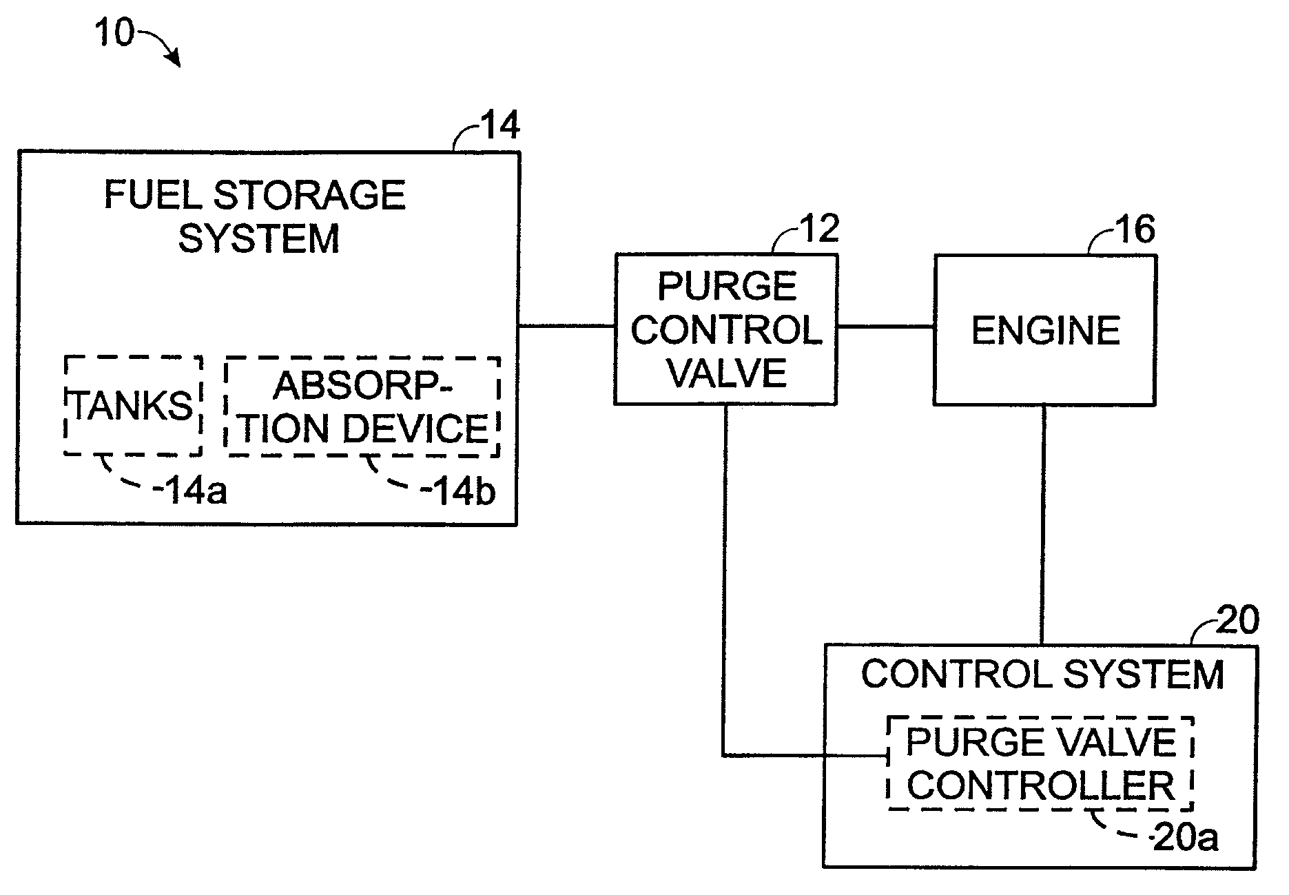
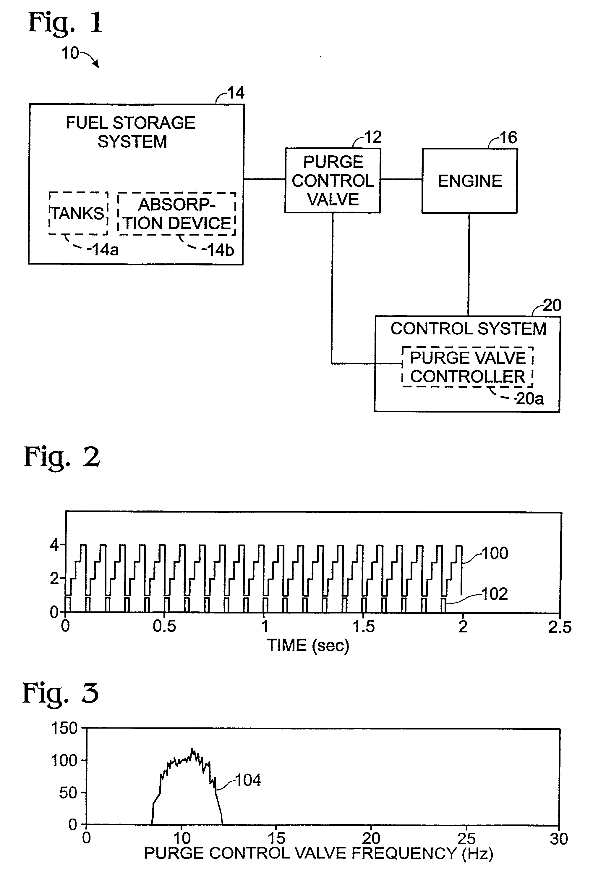
[0020] The present disclosure relates to the control of pulse-width-modulated valves, such a purge control valve used with an internal combustion engine. FIG. 1 schematically shows a purge fuel delivery system 10, which includes a pulse-width-modulated valve in the form of a purge control valve 12. Purge control valve 12 is operatively interposed between a fuel storage system 14 and an internal combustion engine 16.

[0021] The fuel storage system can include one or more tanks 14a configured to hold liquid fuel and one or more absorption devices 14b configured to at least temporarily hold evaporated fuel. The purge control valve can be used to at least partially control a flow rate of air flowing through absorption devices 14b and into the engine, purging the stored fuel out of the absorption device while the engine is running. The purge air / fuel mixture which exits from the absorption device can flow through the purge control valve and then into the intake manifold of the engine. Th...


PUM


Abstract

A system and method for controlling the introduction of purge fuel vapor into a multi-cylinder internal combustion engine is provided. According to one aspect of the disclosure, a schedule for opening and closing an on-off, pulse-width-modulated, purge control valve is predetermined, and the purge control valve is opened and closed according to the predetermined schedule. According to one aspect of the disclosure, a predetermined schedule can include a repeating sequence of on-pulse frequencies.

Description

FIELD [0001] The present disclosure is directed toward a system and method for controlling the introduction of purge fuel vapor into a multi-cylinder internal combustion engine. BACKGROUND AND SUMMARY [0002] Many multi-cylinder internal combustion engines include an evaporative fuel recovery system, in which fuel vapors vented from the fuel tank and captured in a carbon canister are drawn into the engine, where they are combusted along with fuel delivered by fuel injectors. Such systems can include a purge control valve, which controls the flow rate of canister purge fuel vapors entering the engine. Some purge control valves are on-off, pulse-width modulated valves, which are designed to be either fully open or fully closed. Pulse-width modulated valves can be driven by an electrical input signal which is high for a fraction of the signal period and low for the remainder of the signal period. The high portion of the signal is called the on-pulse. The valve opens to allow purge fuel ...

Claims


Application Information

Patent Timeline
Patent Type & Authority Applications(United States)
IPC IPC(8): F02M25/08
CPCF02M25/0836
Inventor CLEMENS, DAVID
Owner FORD GLOBAL TECH LLC
Learn More