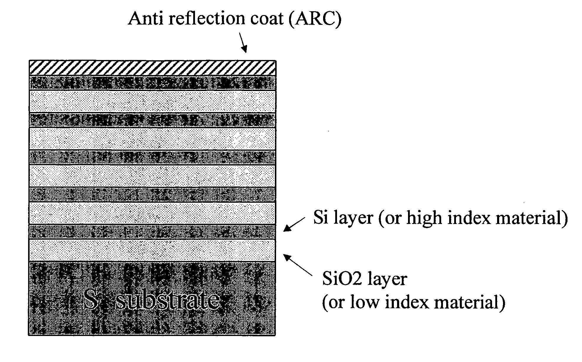
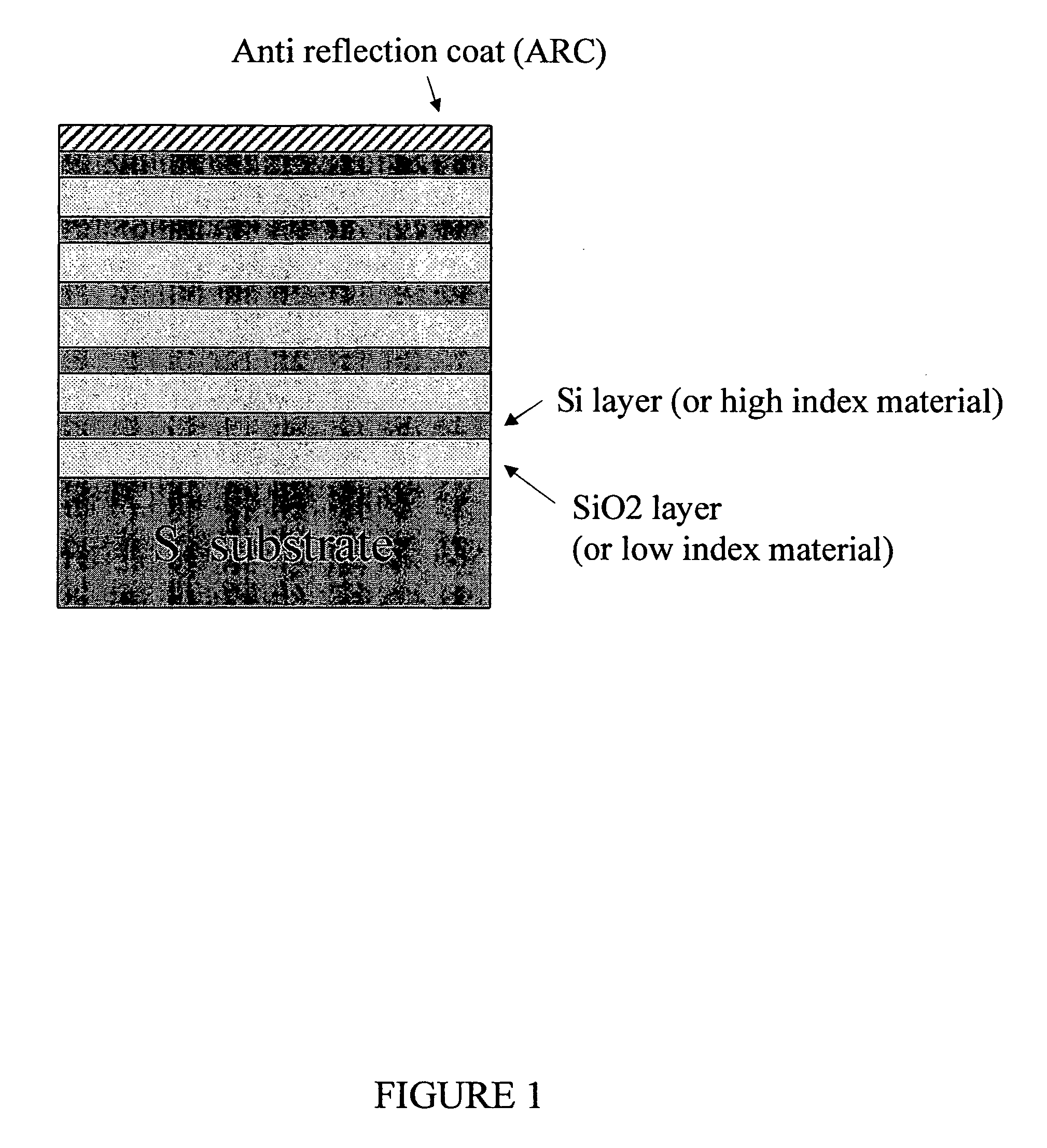
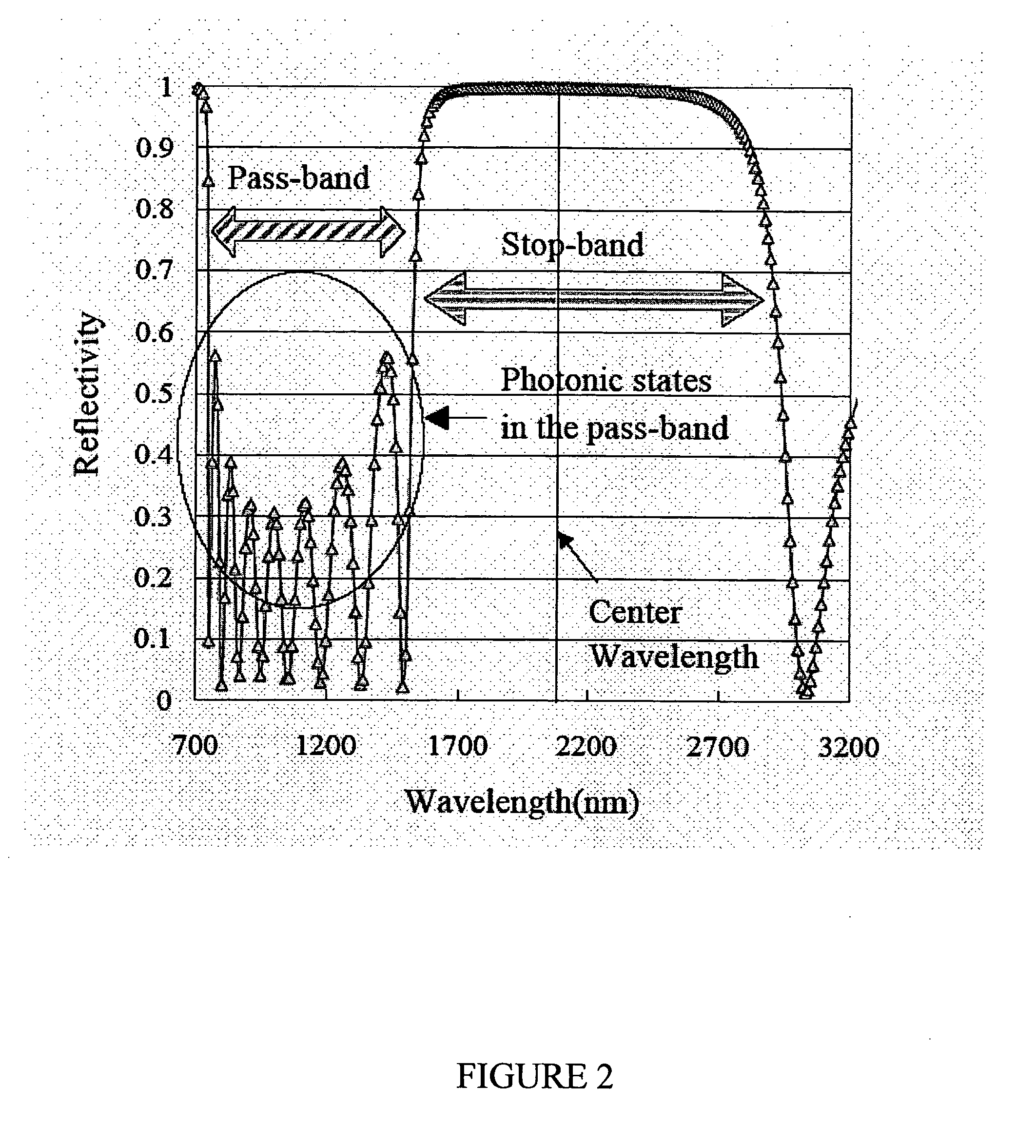
Anti-reflection coating for the pass-band of photonic bandgap crystal
a technology of photonic bandgap crystal and anti-reflection coating, which is applied in the direction of optical waveguide light guide, instruments, nanotechnology, etc., can solve the problems of unsuitable photonic state and simple concept not applicable to pbg, and achieve the effect of high light reflection, maximum light transmission through pass-band, and high light reflection
- Summary
- Abstract
- Description
- Claims
- Application Information
AI Technical Summary
Benefits of technology
Problems solved by technology
Method used
Image

Examples
Embodiment Construction
[0016] While this invention is illustrated and described in a preferred embodiment, the invention may be produced in many different configurations. There is depicted in the drawings, and will herein be described in detail, a preferred embodiment of the invention, with the understanding that the present disclosure is to be considered as an exemplification of the principles of the invention and the associated functional specifications for its construction and is not intended to limit the invention to the embodiment illustrated. Those skilled in the art will envision many other possible variations within the scope of the present invention.
[0017] The present invention makes it possible to obtain the maximum transmission through pass-band of photonic bandgap crystal, which is often referred to as PBG, while preserving the high reflection for stop-band. This characteristic is useful for wavelength filter of photovoltaic devices, laser optics device, etc.
[0018] The present invention prov...
PUM
 Abstract
Description
Claims
Application Information
 - R&D
- Intellectual Property
- Life Sciences
- Materials
- Tech Scout
- Unparalleled Data Quality
- Higher Quality Content
- 60% Fewer Hallucinations
Browse by: Latest US Patents, China's latest patents, Technical Efficacy Thesaurus, Application Domain, Technology Topic, Popular Technical Reports.
© 2025 PatSnap. All rights reserved.Legal|Privacy policy|Modern Slavery Act Transparency Statement|Sitemap|About US| Contact US: help@patsnap.com