
Wireless communication system and wireless communication apparatus

a wireless communication and wireless communication technology, applied in the field of wireless communication systems and wireless communication apparatuses, can solve problems such as system quality degradation, and achieve the effect of effective network operation

Active Publication Date: 2007-03-08
REDWOOD TECHNOLOGIES LLC
View PDF4 Cites 62 Cited by
  • Summary
  • Abstract
  • Description
  • Claims
  • Application Information

AI Technical Summary

Benefits of technology

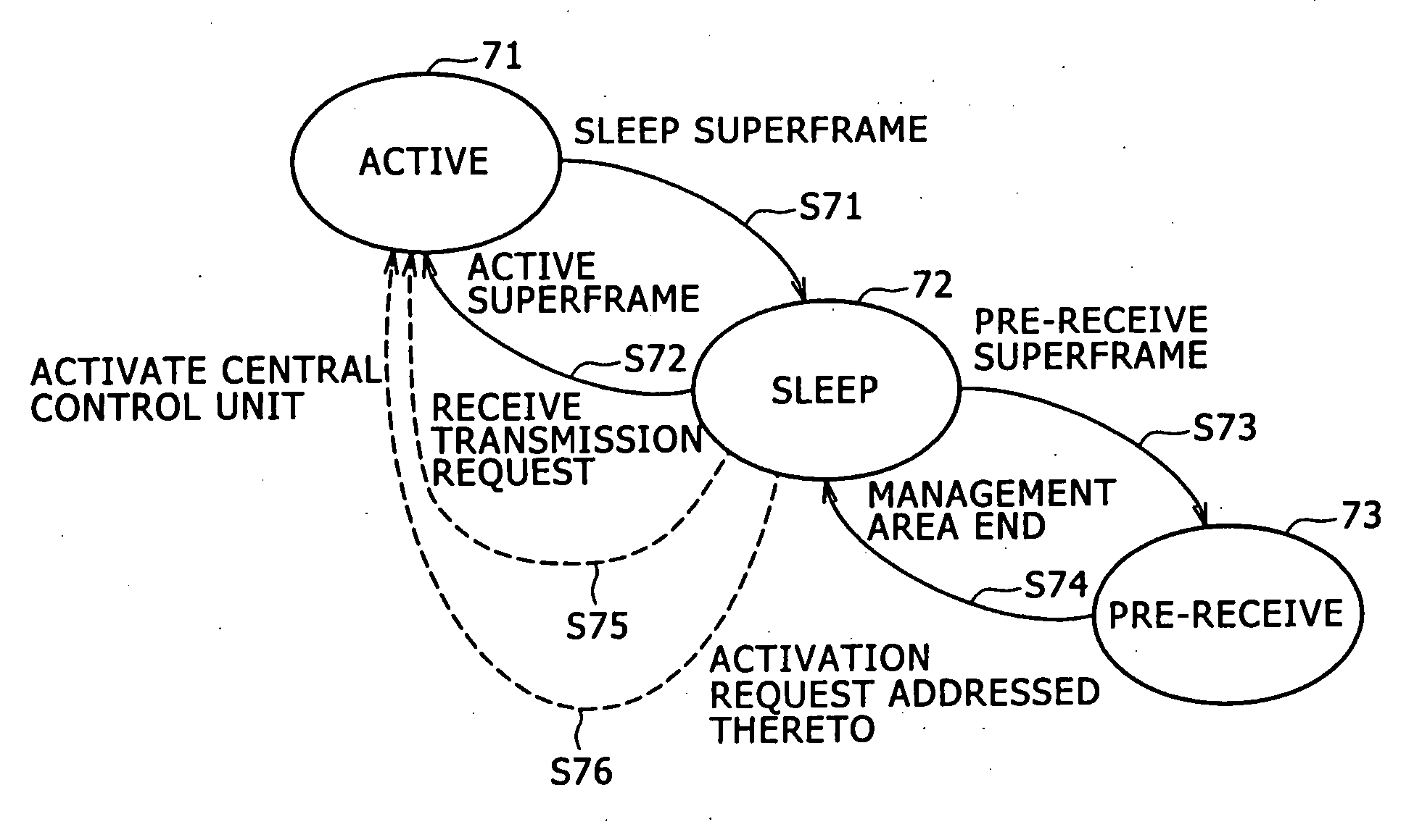
[0019] Alternatively, in the above-described wireless communication system, in the case where the beacon signal received by the wireless communication apparatus in the pre-receive state contains information concerning an activation request addressed thereto, the wireless communication apparatus transitions to the active state. Thus, at the time of transitioning from the sleep state to the active state, the wireless communication apparatus can be activated with sufficient time. In general, it is necessary to have sufficient time (e.g., several hundreds of milliseconds) in order to activate a software section in the process of transition from the sleep state to the active state. In the past, no data can be sent during a time interval between beacon signals such as about 40 milliseconds to 60 milliseconds, thereby causing degradation of system quality. According an embodiment of the invention, there is defined a pre-receive state in which the wireless communication apparatus receives a beacon signal but does not perform beacon signal transmission and data transmission afterward. Thus, the wireless communication apparatus in the pre-receive state can activate the software section while essentially keeping the hardware section in the sleep state.
[0046] Furthermore, by receiving all the adjacent beacon signals before transitioning to the active state, there is an effect that the wireless communication apparatus can grasp its own beacon transmission timing autonomously regardless of the order of transmission positions of beacon signals.

Problems solved by technology

In the past, no data can be sent during a time interval between beacon signals such as about 40 milliseconds to 60 milliseconds, thereby causing degradation of system quality.

Method used


Image

  • Wireless communication system and wireless communication apparatus
  • Wireless communication system and wireless communication apparatus
  • Wireless communication system and wireless communication apparatus

Examples


first embodiment

(A) First Embodiment

[0078] A first embodiment of the present invention will be described.

(1) Configuration of an Ad-Hoc Network

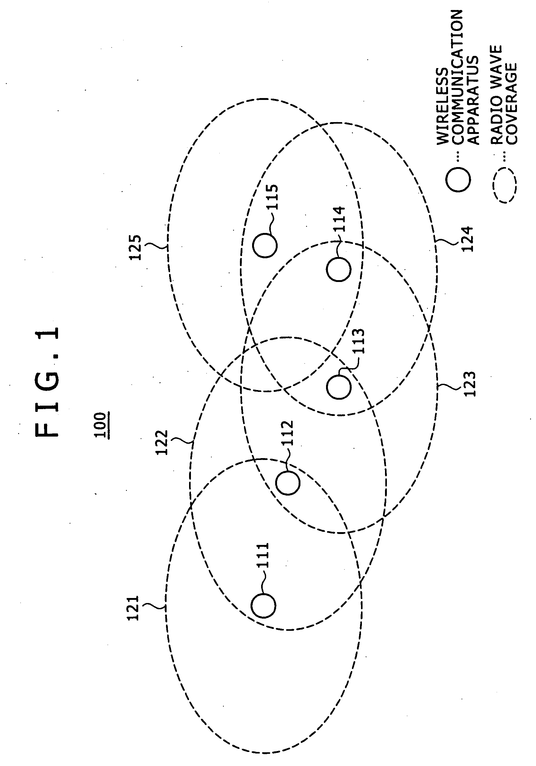
[0079]FIG. 1 shows the configuration of an ad-hoc network. There are shown five adjacent wireless communication apparatuses 111 to 115 constituting an ad-hoc network 100 in FIG. 1 by way of example. In this embodiment, the wireless communication apparatus signifies an apparatus that can perform at least wireless communication, but is not limited to an apparatus that can perform only wireless communication.

[0080] An area indicated by dashed lines in FIG. 1 represents the radio wave coverage of a wireless communication apparatus situated at the center thereof. That is, the wireless communication apparatus 111 can communicate with the wireless communication apparatus 112 within a radio wave coverage 121. The wireless communication apparatus 112 can communicate with the wireless communication apparatus 111 and the wireless communication apparatus 113 within ...

second embodiment

(B) Second Embodiment

[0144] A second embodiment of the present invention will be described.

[0145] As described in the first embodiment, there is adopted a method of detecting a beacon slot unoccupied by the adjacent wireless communication apparatuses by informing each other about the use status of the immediately preceding beacon slots among the wireless communication apparatuses constituting the ad-hoc network. That is, each wireless communication apparatus receives the beacon signals from the adjacent wireless communication apparatuses and describes the received beacon slots as “occupied.” Further, there is adopted a method of operating a network in such a manner that a wireless communication apparatus using the last beacon slot substitutes an unoccupied beacon slot for the last beacon slot thereby maintaining as short a beacon period as possible.

[0146] However, in the hibernation mode described in the first embodiment, since a beacon signal is not transmitted from a wireless co...

third embodiment

(C) Third Embodiment

[0201] A third embodiment of the present invention will be described.

[0202] As a media access technology applied to a wireless personal area network (PAN), IEEE802. 15. 3 is being studied, and as an access scheme of multi-band OFDM (MB-OFDM), a Distributed_MAC draft specification is being studied. It is possible to use the hibernation mode (sleep mode) in which a wireless communication apparatus transitions to the active state of one superframe after transitioning to the sleep state over a plurality of superframes as described in the first and second embodiments, as a setting method of a sleep state for the low power consumption operation defined in IEEE802. 15. 3 or Distributed_MAC.

[0203] Distributed_MAC defines a structure for exchanging various kinds of information and parameters using beacon frames exchanged between adjacent communication apparatuses during a beacon period in a superframe. More specifically, it is structured such that requests and responses...


PUM


Abstract

A wireless communication system includes plural wireless communication apparatuses which form an ad-hoc network. In the system, an operating state of each superframe of each wireless communication apparatus is determined from three operating states: an active state in which beacon signal transmission / reception and data transmission / reception are performed as necessary; a sleep state in which beacon signal transmission / reception and data transmission / reception are not performed; and a pre-receive state in which a beacon signal is received and afterward beacon signal transmission and data transmission are not performed.

Description

CROSS-REFERENCE TO RELATED APPLICATIONS [0001] The present invention claims priority from Japanese Patent Application Nos. 2004-303474 filed Oct. 18, 2004, 2005-119348 filed Apr. 18, 2005, and 2005-265707 filed Sep. 13, 2005, the disclosures of which are hereby incorporated by reference herein. BACKGROUND OF THE INVENTION [0002] The present invention relates to a wireless communication system and a wireless communication apparatus, and more particularly, to a wireless communication system and a wireless communication apparatus that are characterized in a method of returning to an active state from a sleep state in an ad-hoc network. [0003] At present, a standard specification to achieve a high-speed wireless personal area network (PAN) is defined in IEEE802. 15. 3 and is being recognized as one of the high-speed wireless communication systems. For example, International Publication WO 2004 / 071020 pamphlet defines a method by which one activation is carried out in a plurality of supe...

Claims


Application Information

Patent Timeline
IPC IPC(8): H04B7/185
CPCH04W48/08H04W48/16H04W52/0219H04W52/0216H04W84/18Y02D30/70
Inventor SUGAYA, SHIGERU
Owner REDWOOD TECHNOLOGIES LLC
Learn More