
Cookware with flat interior surface

Active Publication Date: 2007-03-08
MEYER INTPROP
View PDF5 Cites 7 Cited by
  • Summary
  • Abstract
  • Description
  • Claims
  • Application Information

AI Technical Summary

Benefits of technology

[0007] It is another object of the invention to provide an efficient and economical process for manufacturing a cooking vessel havi

Problems solved by technology

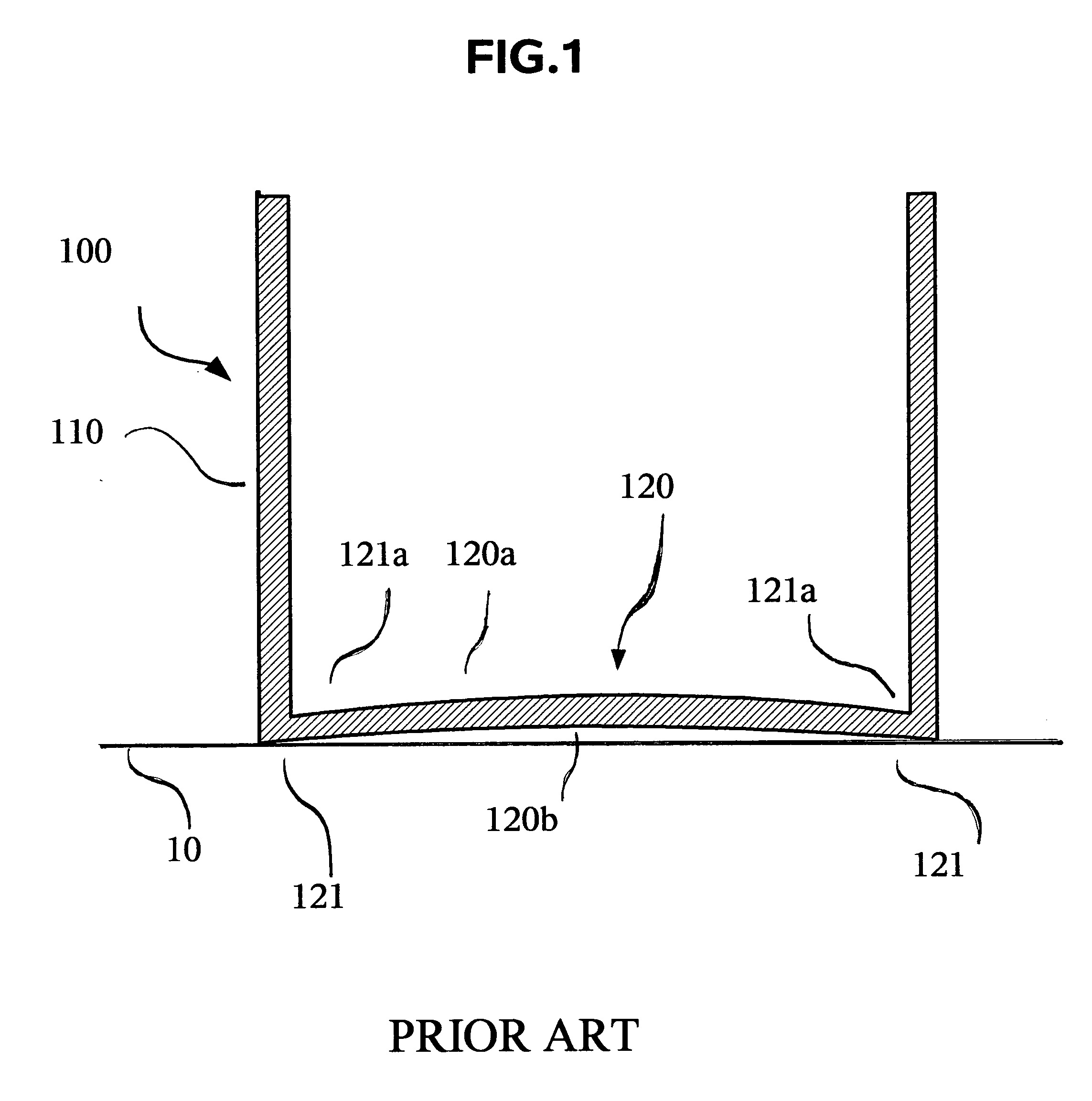
Although consumer are largely used to a slightly convex interior surface, it is undesirable if one is trying to minimize the use of cooking oil.

Method used


Image

  • Cookware with flat interior surface
  • Cookware with flat interior surface
  • Cookware with flat interior surface

Examples


Embodiment Construction

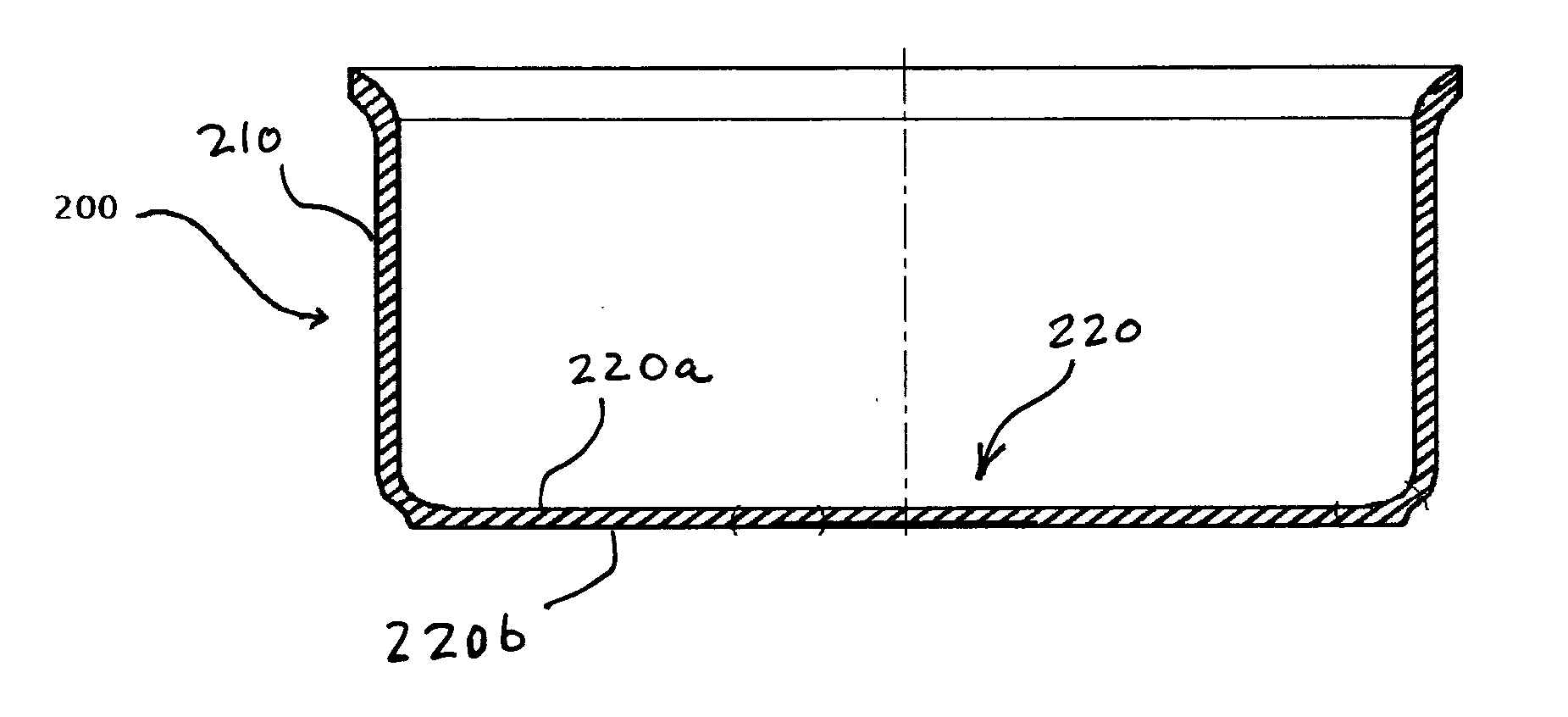
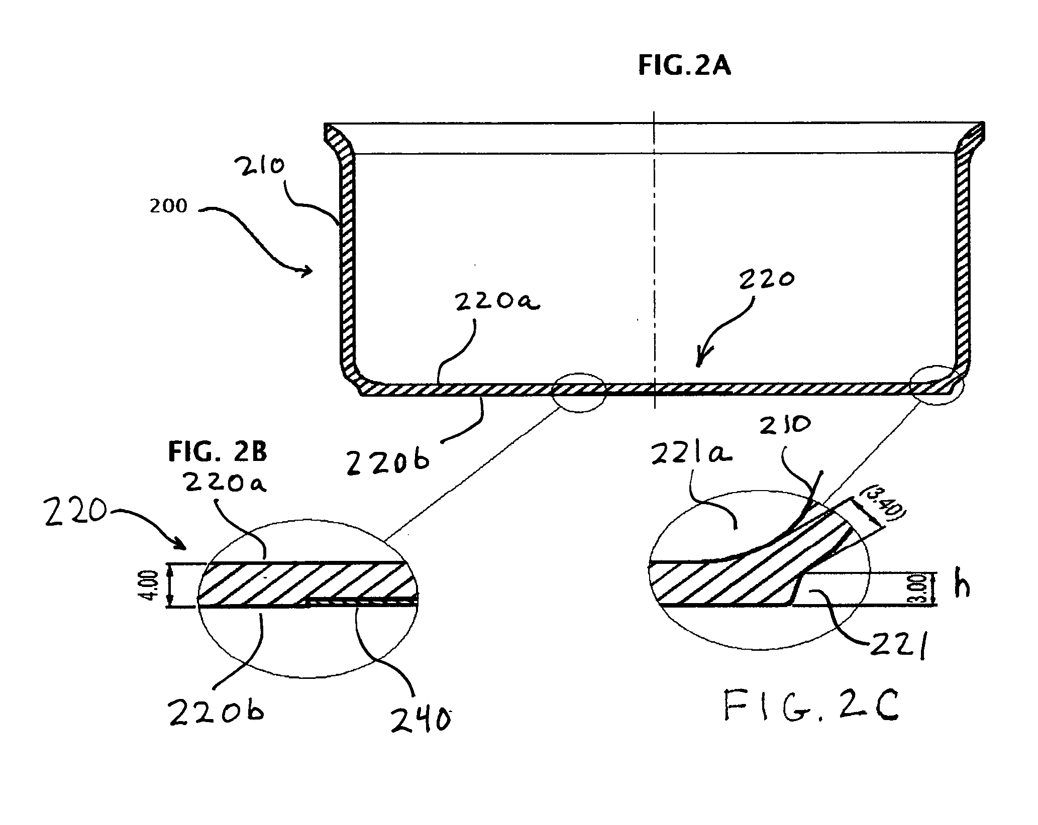
[0020] Referring to FIGS. 2 through 7, wherein like reference numerals refer to like components in the various views, there is illustrated therein a new and improved article of cookware, generally denominated 200 herein.

[0021]FIG. 1 illustrates a prior art article of cookware 100. The article 100 is optionally a pan or pot, depending on the relative diameter of the bottom 120 to the height of the surrounding and substantially upright sidewall 110, which together form a fluid containing vessel. The article 100 has an inner bottom cooking surface 120a which receives foodstuffs, cooking oil and the like, whereas the outer bottom cooking surface 120b rests on a table, heating element, burner grid and the like. Accordingly, the article of cookware 100 is shown in FIG. 1 as resting on surface 10. It is desirable that the article of cookware 100 rest firmly on a planar surface and not spin or otherwise move when foodstuff inside the article 100 are manipulated, primary by stirring. Accord...


PUM

PropertyMeasurementUnit
Shapeaaaaaaaaaa

Abstract

An article of cookware is fabricated by a combination of a deep drawing a metal sheet or laminate to form a fluid retaining preform and then using an impact bonding process to attach a medallion to the outside bottom surface of preform. In another aspect, the impact bonding process alternatively provides a means to achieve a slightly concave exterior bottom surface, while maintaining a substantially flat and / or slightly concave interior bottom surface to minimize the use of cooking oil.

Description

BACKGROUND OF INVENTION [0001] The present invention relates to an improved article of cookware, in particular a pot or pan having a flat interior surface. [0002] Cookware article such as pots and pans are routinely formed in a process that provides for the exterior bottom surface to have a concave shape, so that the pan rests on the periphery of the exterior bottom surface when disposed on a flat planar surface. This precludes the pots from turning or spinning, as would occur if the bottom where slightly convex so that the pan was supported by a small point or area at the center of the bottom surface. [0003] However, fabricating methods that create a concave outer exterior surface, also create a convex interior surface. Although consumer are largely used to a slightly convex interior surface, it is undesirable if one is trying to minimize the use of cooking oil. Oil poured into the center will run toward the interior edges of the pan, thus a larger quantity of oil is required to ev...

Claims


Application Information

Patent Timeline
IPC IPC(8): A47J37/01
CPCY10T29/49908A47J27/002
Inventor CHENG, STANLEY KIN SUI
Owner MEYER INTPROP
Learn More