
Optical disk drive

a technology of optical disk drive and fusing head, which is applied in the direction of data recording, instruments, information storage, etc., can solve the problems of affecting the motor's magnetic force, affecting taking a lot of labor and time to place the damper yoke and the fusing of the head, so as to reduce the number of components and manufacturing steps, the effect of shortening the manufacturing time and reducing the number of components

Inactive Publication Date: 2007-03-01
FUNAI ELECTRIC CO LTD
View PDF8 Cites 1 Cited by
  • Summary
  • Abstract
  • Description
  • Claims
  • Application Information

AI Technical Summary

Benefits of technology

The present invention provides an optical disk drive with a clamp mechanism for holding an optical disk between a clamp and a turntable to drive the optical disk. The clamp mechanism can be manufactured in a short time at a low cost by reducing the number of components and manufacturing steps. The clamp mechanism includes a presser portion, an engaging recess, and a ring-like damper magnet. The optical disk placement portion and the protruding portion of the turntable are made of a magnetic metal plate, which simplifies the manufacturing process and reduces the influence of the magnetic field on the motor. The clamp includes a presser portion with a pressing face that contacts with the optical disk opposite to the side that contacts with the turntable. The optical disk placement portion is made of a magnetic metal plate by a drawing process, which makes the process easier and reduces the number of structural members. The optical disk placement portion and the protruding portion of the turntable are fixed together using bosses and fused tips, and the holding force of the optical disk is achieved by the magnetic field formed by the damper magnet in the clamp. The optical disk drive with the clamp mechanism can reduce the influence of the magnetic field on the motor, and the manufacturing process is easier and faster than traditional methods.

Problems solved by technology

Therefore, the positioning of the damper yoke 924 as well as the fusing of the bosses 926 takes much labor and time.
This magnetic force may give a bad influence to the motor 94.

Method used


Image

  • Optical disk drive
  • Optical disk drive
  • Optical disk drive

Examples


Embodiment Construction

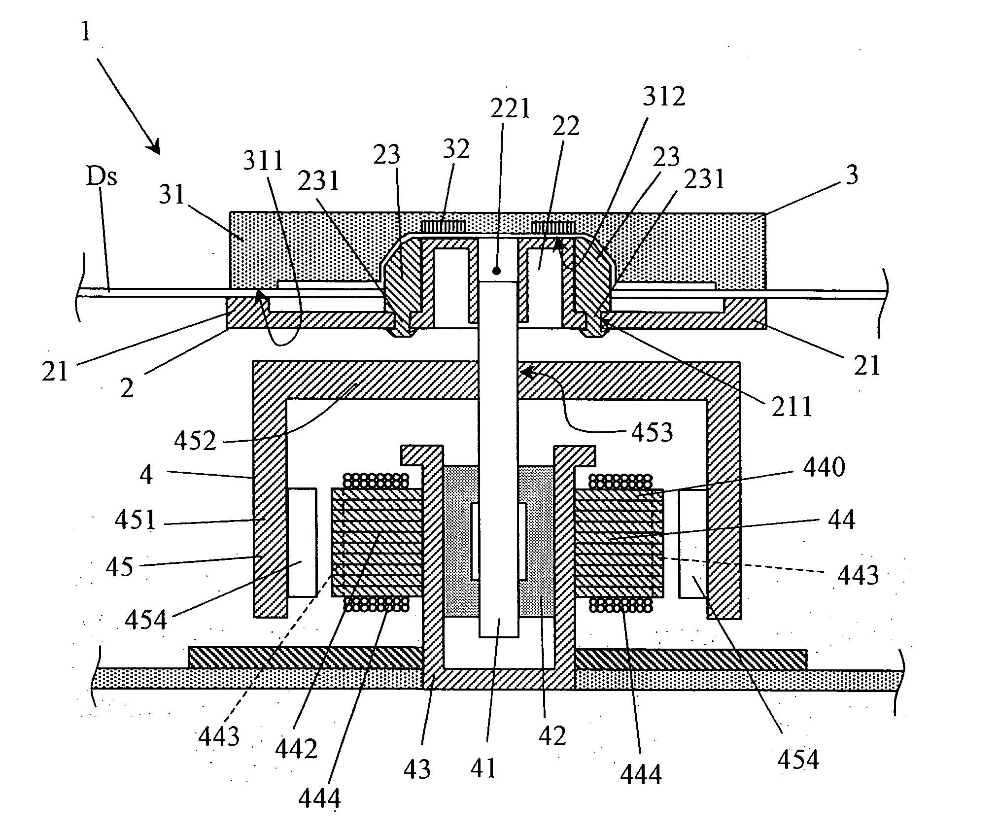
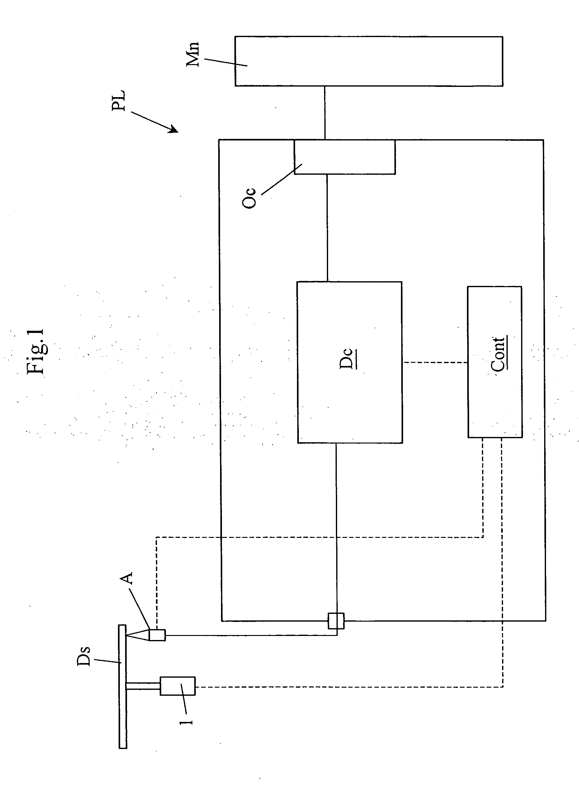
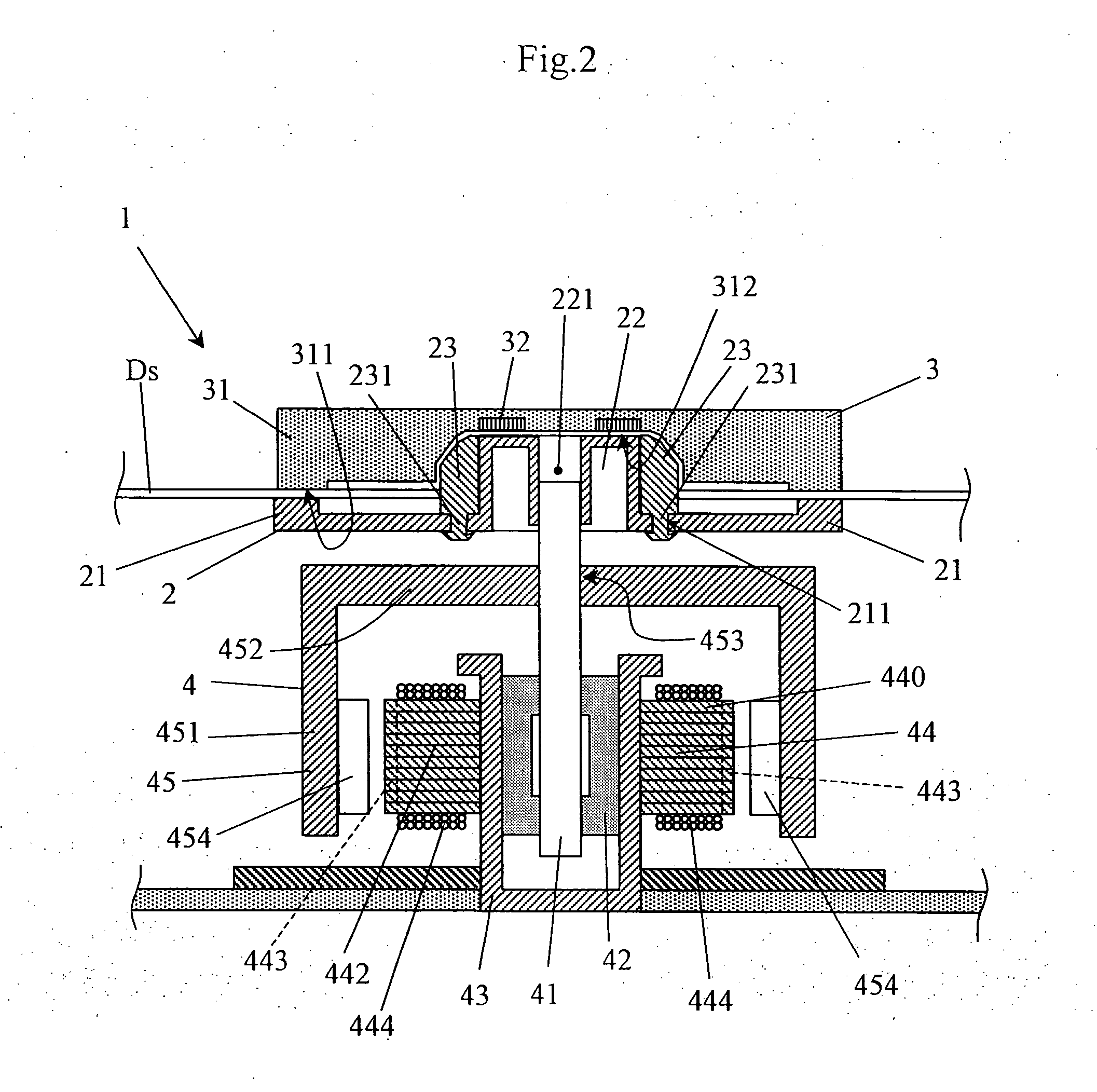
[0031] Now, an example of the present invention will be described with reference to the attached drawings. FIG. 1 is a block diagram showing a structure of an optical disk drive according to the example of the present invention. The optical disk drive shown in FIG. 1 is a DVD player, but an application of the present invention is not limited to a DVD player. A DVD player PL shown in FIG. 1 includes an optical disk drive mechanism 1 for rotating an optical disk (a DVD recording medium) Ds, an optical head A for reading information from the optical disk Ds by irradiating the optical disk Ds with a light beam, a decoder Dc for decoding a signal detected by the optical head A, an external connection portion Oc for connection with a monitor Mn that is an external display device and a control portion Cont.

[0032] The DVD player PL is controlled by the control portion Cont. When a user issues a command for reproducing information recorded on a DVD, the optical disk drive mechanism 1 first ...


PUM

PropertyMeasurementUnit
magneticaaaaaaaaaa
magnetic forceaaaaaaaaaa
temperatureaaaaaaaaaa

Abstract

An optical disk drive includes a turntable, a clamp and a motor for driving the turntable to rotate. An optical disk is held in such a way that it is sandwiched between the turntable and the clamp. The turntable, which is made of a magnetic metal plate by a drawing process, includes an optical disk placement portion for placing an optical disk and a protruding portion that protruded from the center of the optical disk placement portion in the axial direction.

Description

[0001] This application is based on Japanese Patent Application No. 2005-239572 filed on Aug. 22, 2005, the contents of which are hereby incorporated by reference. BACKGROUND OF THE INVENTION [0002] 1. Field of the Invention [0003] The present invention relates to an optical disk drive for writing and reading data on an optical disk by irradiating the optical disk with a laser beam. In particular, the present invention relates to an optical disk drive that is capable of holding the optical disk securely. [0004] 2. Description of Related Art [0005] Optical disks are used as recording media for recording and / or reading information such as picture data or sound data by irradiating the optical disk with a laser beam. As an optical disk, a CD (Compact Disc), a DVD (Digital Versatile Disc) or the like is used widely. An optical disk drive that uses such an optical disk as a recording medium rotates the optical disk and irradiates a recording surface of the optical disk with a laser beam, ...

Claims


Application Information

Patent Timeline
Patent Type & Authority Applications(United States)
IPC IPC(8): G11B17/04
CPCG11B17/0284G11B17/0282
Inventor SHINMI, TSUKASATANAKA, SHINYA
Owner FUNAI ELECTRIC CO LTD
Learn More