
Lighting unit for vehicle

a technology for vehicle lighting and vehicle body, applied in the direction of cycle equipment, lighting and heating apparatus, optical signal, etc., can solve the problems of limit in trying to improve visibility, and achieve the effect of increasing visibility

Inactive Publication Date: 2007-03-01
HONDA MOTOR CO LTD
View PDF5 Cites 40 Cited by
  • Summary
  • Abstract
  • Description
  • Claims
  • Application Information

AI Technical Summary

Benefits of technology

[0008] An object of the present invention is to further increase visibility with an enlarged light emitting range using design processing to form a light emitting section that is discontinuous from a projector lamp by causing a peripheral section isolated from the projector lamp to partially emit light.
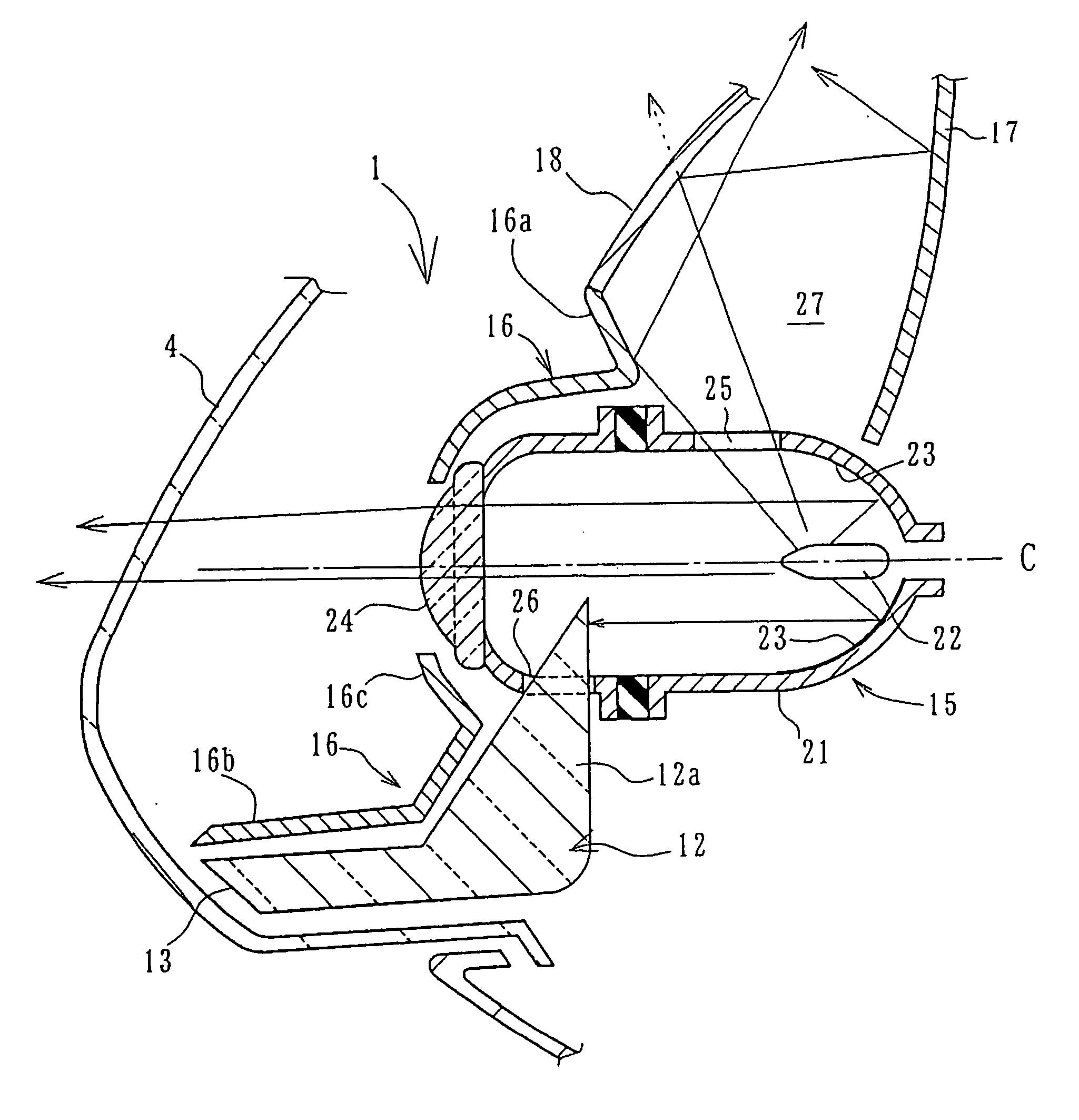
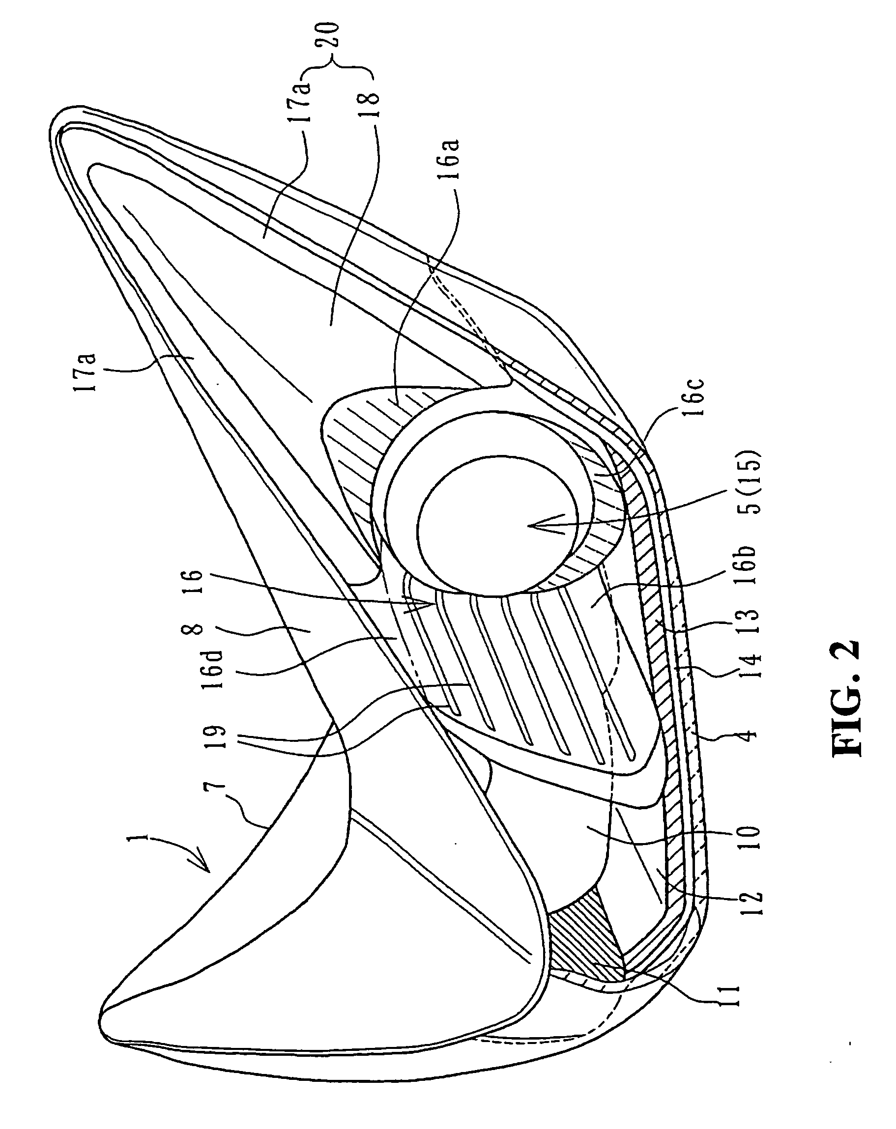
[0015] According to the first aspect of the present invention, an isolated extension section is provided extending out so as to come away from the projector lamp is provided, a light guiding path formed by a first reflector positioned behind the projector lamp for reflecting light forwards, and a second reflector covering a front part of the first reflector for reflecting light to the rear, is provided in the isolated extension section, and it is possible to form an isolated light emitting section for emitting light using light that has been guided from the projector lamp by the light guiding path being provided at a position of the isolated extension section away from the projector lamp. It is therefore possible to enlarge a light emitting range as far as a position isolated from the projector lamp, and it also possible to increase visibility beyond that obtained by simply increasing the light emitting surface area, due to the fact that freedom of design of the projector lamp and the isolated light emitting region is brought about. Also, the light guiding path can be formed with a simple structure and cheaply, and it is possible to prevent an increase in a light source because light emission is performed using light of the projector lamp.
[0017] According to the third aspect of the present invention, the isolated light emitting section is provided so as to fringe at least part of the isolated extension section. Therefore, it is possible to improve the design effect of the light.
[0019] According to the fifth aspect of the present invention, the second reflector is semitransparent, allowing the guided light to partially pass through, and overall performs plane emission. Therefore, it is possible to improve both designability and visibility.
[0020] According to the sixth aspect of the present invention, the lighting unit is a front light provided in a vehicle body cover for covering the front of a motorcycle, and the isolated extension section is formed along a side surface of the vehicle cover. Therefore, it becomes possible to freely form the isolated extension section sufficiently large using a side surface of the vehicle cover, and it is possible to improve both design freedom and visibility.

Problems solved by technology

However, the effect of this on improved visibility is only proportional to the light emitting surface area.
Therefore, there are evidently limitations in trying to improve visibility simply by enlarging the light emitting surface area.

Method used


Image

  • Lighting unit for vehicle
  • Lighting unit for vehicle
  • Lighting unit for vehicle

Examples


Embodiment Construction

[0029] An embodiment of the present invention will now be described with reference to the accompanying drawings. The same reference numerals will be used to identify the same or similar elements throughout the several views.

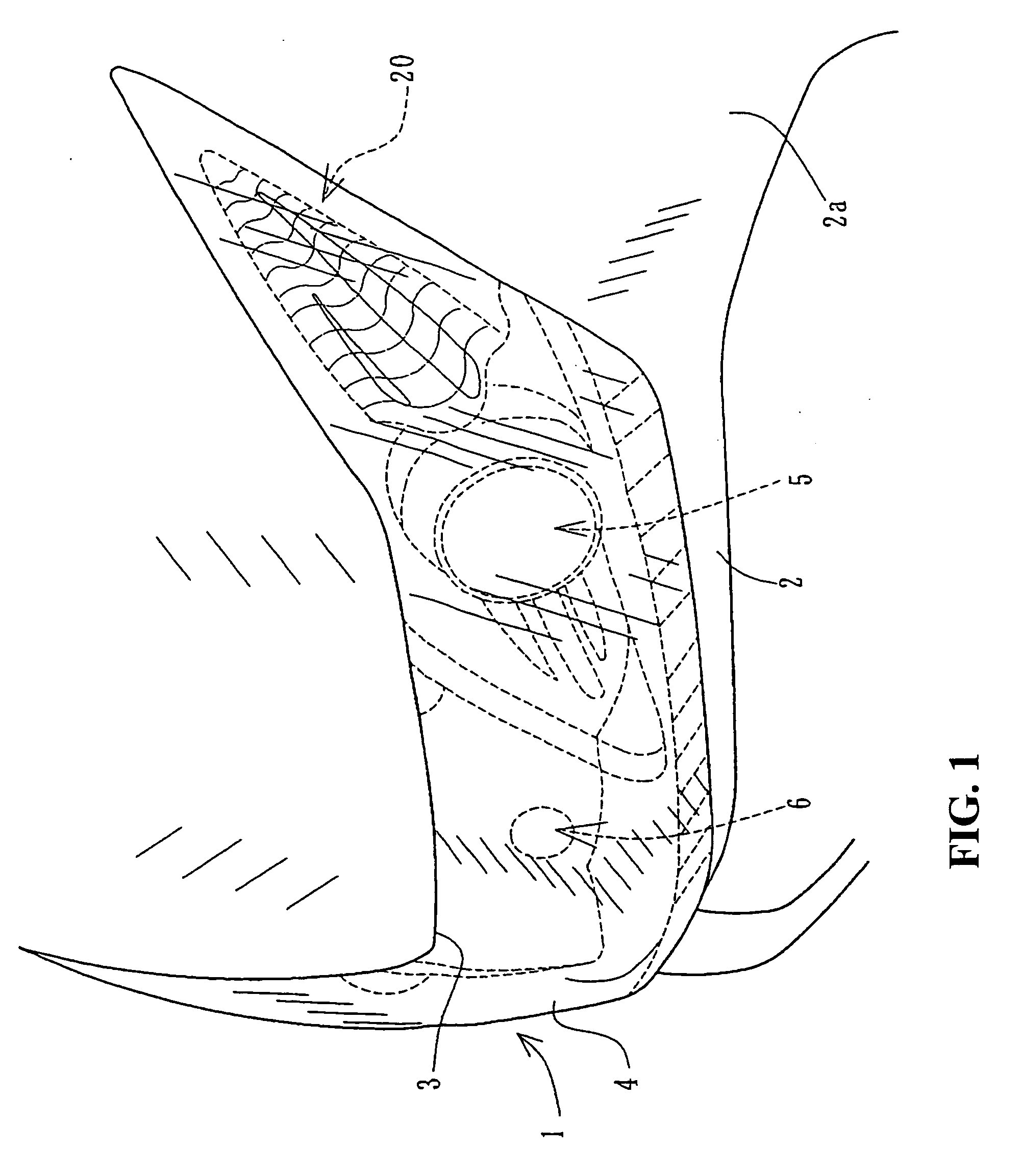
[0030]FIG. 1 is a perspective drawing showing a front light 1 for a motorcycle relating to this embodiment. The front light 1 is fitted into a front light attachment hole 3 formed in the front of an upper cowl 2 covering a front end section of the vehicle, as part of a vehicle cover. The front surface is covered by an outer lens 4, which is a transparent cover lens. A projector lamp type low beam lamp 5 is provided at an inner side section of the outer lens 4, and a high beam lamp 6 is arranged in the center.

[0031] An isolated extension section 20, that will be described later, being part of the front light 1, and a section extending outwards diagonally upwards from the low beam lamp 5 are formed comparatively largely along a side surface 2a of the upper cowl 2...


PUM


Abstract

To improve visibility by expanding a light emitting range without increasing a size of a light source, in a lighting unit for a vehicle using a projector lamp. A front light has a projector lamp arranged behind an outer lens. A light guiding body is provided from a side surface of the projector lamp to the front. A front surface of the light guiding body emits light along a bottom surface of the front light. A first reflector and a second reflector constituting an isolated extension section extending upwards are arranged opposite to each other holding a distance between them, at a side surface of the projector lamp. The periphery of the first reflector extends out slightly more than the second reflector to form a fringe light emitting section. This causes emission of light of the light guide path in a fringe shape.

Description

CROSS-REFERENCE TO RELATED APPLICATIONS [0001] This nonprovisional application claims priority under 35 U.S.C. § 119(a) on Patent Application No. 2005-251460, filed in Japan on Aug. 31, 2005, the entirety of which is incorporated herein by reference. BACKGROUND OF THE INVENTION [0002] 1. Field of the Invention [0003] The present invention relates to a lighting unit for a vehicle using a projector lamp. In particular, the present invention relates to a lighting unit for a vehicle using a projector lamp that increases the visibility while not increasing the size of light source. [0004] 2. Description of Background Art [0005] A projector lamp that irradiates light from a light source after concentrating the light source using a convex lens is known. However, a projector lamp according to the background art has a small light emitting surface area and reflection surface for intensifying the light. This means that a light guiding member for improving visibility must be attached (see Japan...

Claims


Application Information

Patent Timeline
IPC IPC(8): B60Q1/00F21Y101/00
CPCB60Q1/0011B60Q1/0041F21S48/1388F21S48/1241B62J6/02B62J6/024B62J6/026F21S41/162F21S41/321F21S41/365F21S43/241F21S43/243F21S43/249F21S43/31F21S43/315
Inventor KOGO, SATOSHIOHASHI, HAYATO
Owner HONDA MOTOR CO LTD
Learn More