
Filter and antenna duplexer

a filter and duplexer technology, applied in the direction of impedence networks, electrical apparatus, piezoelectric/electrostrictive/magnetostrictive devices, etc., can solve the problems of reducing the size of the filter and the duplexer, the inability to arbitrarily set two antiresonance points, and the design flexibility of the filter degrade, so as to improve the design flexibility, reduce the mounting area, and reduce the excitation efficiency

Active Publication Date: 2007-03-01
TAIYO YUDEN KK
View PDF10 Cites 23 Cited by
  • Summary
  • Abstract
  • Description
  • Claims
  • Application Information

AI Technical Summary

Benefits of technology

[0016] The present invention has been made in view of the above circumstances and provides a filter and an antenna duplexer that can be downsized or improve the design flexibility.
[0017] According to one aspect of the present invention, preferably, there is provided a filter including: a first resonator; a second resonator in which an excitation efficiency is reduced more than the first resonator; and an inductor connected in parallel with the second resonator. It is possible to reduce the mounting area and improve the attenuation of an arbitrary frequency. Accordingly, it is possible to provide a filter that can be downsized or improve the design flexibility.
[0018] According to another aspect of the present invention, preferably, there is provided a ladder type filter including: one or more series resonators; one or more parallel resonators; a first resonator; a second resonator in which an excitation efficiency is reduced more than the first resonator; and an inductor connected in parallel with the second resonator. At least one of the one or more series resonators and the one or more parallel resonators is the second resonator. Accordingly, it is possible to provide a ladder type filter of a small mounting area that can improve the attenuation at an arbitrary frequency.
[0019] According to another aspect of the present invention, preferably, there is provided a surface acoustic wave filter including: a multi-mode surface acoustic wave filter; a first resonator; a second resonator in which an excitation efficiency is reduced more than the first resonator; and an inductor connected in parallel with the second resonator. The first resonator and the second resonator are made of a piezoelectric thin film resonator or a piezoelectric thin film resonator. Accordingly, it is possible to provide a multi-mode surface acoustic filter of a small mounting area that can improve the attenuation at an arbitrary frequency.
[0020] According to another aspect of the present invention, preferably, there is provided an antenna duplexer including: an antenna terminal; a first filter and a second filter connected to the antenna terminal. At least one of the first filter and the second filter is a filter including: a first resonator; a second resonator in which an excitation efficiency is reduced more than the first resonator; and an inductor connected in parallel with the second resonator. Accordingly, it is possible to provide an antenna duplexer of a small mounting area that can improve the attenuation at an arbitrary frequency.

Problems solved by technology

In the conventional techniques described in Patent Documents 1 through 4, however, the inductor connected in parallel with the resonator has a large size, thereby causing a problem that the sizes of the filter and the duplexer cannot be reduced.
In addition, two antiresonance points cannot be arbitrarily set.
For these reasons, there is another problem in that design flexibility is degraded in the filter that utilizes the two antiresonance points.

Method used


Image

  • Filter and antenna duplexer
  • Filter and antenna duplexer
  • Filter and antenna duplexer

Examples


first embodiment

, and employed in the present invention;

[0050]FIG. 13B is an enlarged view around an antiresonance point 1;

[0051]FIG. 14A is a top view of a normal resonator (resonator 0);

[0052]FIG. 14B is an enlarged view of electrode fingers;

[0053]FIG. 15A is a top view of the resonator (resonator 1) in which the excitation efficiency is reduced;

[0054]FIG. 15B is an enlarged view of the electrode fingers;

[0055]FIG. 16 is a top view of the resonator (resonator 2) in which the excitation efficiency is reduced;

[0056]FIG. 17 is a top view of the resonator (resonator 3) in which the excitation efficiency is reduced;

[0057]FIG. 18A is a top view of the resonator (resonator 4) in which the excitation efficiency is reduced;

[0058]FIG. 18B is an enlarged view of the electrode fingers;

[0059]FIG. 19A is a top view of the resonator (resonator 5) in which the excitation efficiency is reduced;

[0060]FIG. 19B is an enlarged view of the electrode fingers;

[0061]FIG. 20 is a top view of the resonator (reso...

first exemplary embodiment

[0118] A description will now be given of the configuration and principle of the resonant circuit employed in the first exemplary embodiment of the present invention. In a resonator, if the excitation efficiency of the resonator is reduced with the resonance frequency fixed, the resonance frequency does not change and only the antiresonance frequency is lowered. The reduced rate of the excitation efficiency is set to x %, an antiresonance frequency fa is expressed in Expression 6 with a resonance frequency fro and an antiresonance frequency fao, where x=0.

fa=fa0−x(fa0˜fr0)  (Expression 6)

[0119] A description will now be given of a case where the reduced rate x of the excitation efficiency is considered as a parameter in the resonant circuit shown in FIG. 6. FIG. 9A is a block diagram of a resonant circuit in which a resonator S31 which excitation efficiency is reduced is connected between the input terminal In and the output terminal Out. FIG. 9B is a view showing an equivalent ci...

second exemplary embodiment

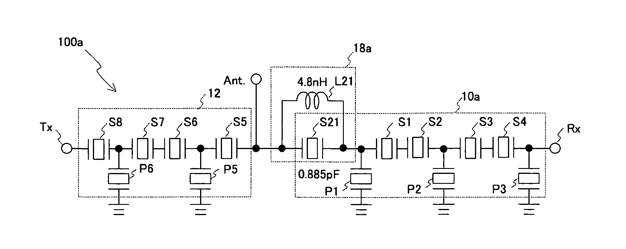
[0149] In a second embodiment of the present invention, the resonant circuit employed in the first embodiment is applied to an antenna duplexer. FIG. 27A through FIG. 27C are block diagrams of the duplexer. FIG. 27A is a block diagram of a duplexer 100a of Conventional Example 2 having the resonant circuit 18a of the conventional example 1 shown in FIG. 12A. FIG. 27B is a block diagram of a duplexer 100b of Comparative Example 2 having the resonant circuit 18b of Comparative Example 1. FIG. 27C is a block diagram of a duplexer 100 having the resonant circuit 18 employed in the first exemplary embodiment in accordance with the second exemplary embodiment of the present invention.

[0150] Referring to FIG. 27C, the duplexer100 employed in the second exemplary embodiment includes a receive filter 10 (first filter) connected between an antenna terminal Ant and a receiving terminal Rx. The duplexer 100 also includes a matching circuit composed of the resonant circuit 18 connected between ...


PUM


Abstract

There is provided a filter including a first resonator, a second resonator in which an excitation efficiency is reduced more than the first resonator, and an inductor connected in parallel with the second resonator.

Description

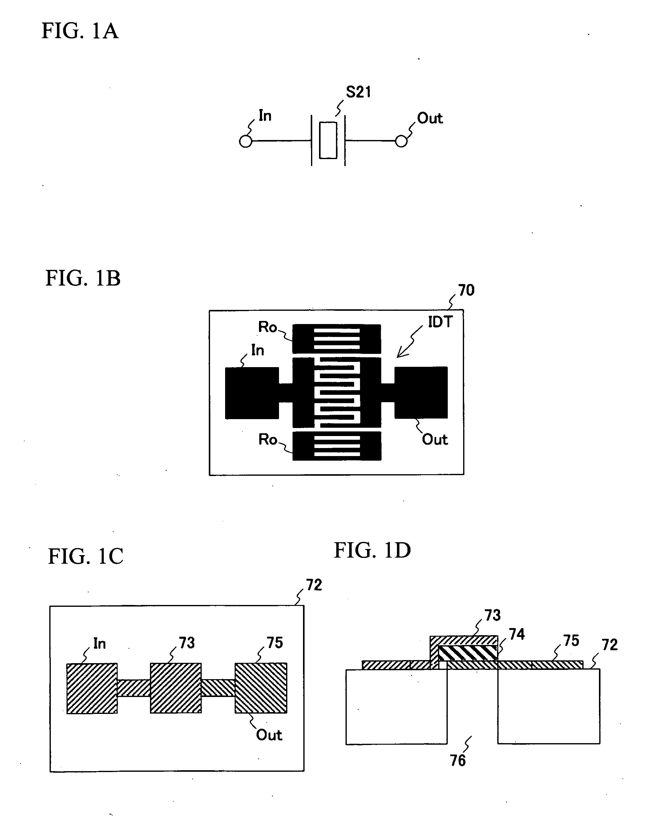
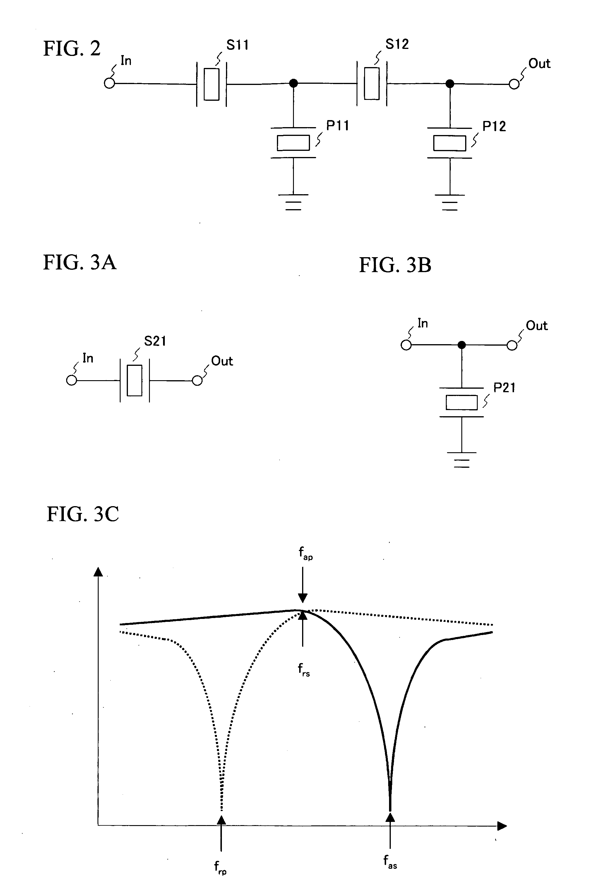
BACKGROUND OF THE INVENTION [0001] 1. Field of the Invention [0002] This invention generally relates to filters and antenna duplexers, and more particularly, to a filter and an antenna duplexer in which an inductor is connected in parallel with a resonator. [0003] 2. Description of the Related Art [0004] In recent years, mobile telephones and mobile information terminals have become widespread rapidly, with the advancements of mobile communications systems. For example, the mobile telephone terminals communicate at high-frequency bands such as 800 MHz to 1.0 GHz and 1.5 GHz to 2.0 GHz. A device for the mobile communication system often employs a high-frequency filter having a resonator or antenna duplexer having the high-frequency filter. [0005] Referring to FIG. 1A, a resonator S21 is arranged between an input terminal In and an output terminal Out to forms a one-port resonant circuit. A Surface Acoustic Wave (SAW) resonator or Film Bulk Acoustic Resonator (FBAR) is employed as a r...

Claims


Application Information

Patent Timeline
Patent Type & Authority Applications(United States)
IPC IPC(8): H03H9/72H03H9/64H03H9/145
CPCH03H9/0042H03H2003/0435H03H9/0576H03H9/14517H03H9/14526H03H9/14547H03H9/14552H03H9/14594H03H9/174H03H9/6483H03H9/706H03H9/72H03H9/725H03H2003/0428H03H9/02157H03H9/64H03H9/54
Inventor INOUE, SHOGONISHIHARA, TOKIHIROMATSUDA, TAKASHIUEDA, MASANORI
Owner TAIYO YUDEN KK
Learn More