
Spray device

Inactive Publication Date: 2007-03-01
HORNBEAM IVY
View PDF18 Cites 13 Cited by
  • Summary
  • Abstract
  • Description
  • Claims
  • Application Information

AI Technical Summary

Benefits of technology

[0009] The present invention aims to ameliorate one or more of the above-mentioned problems. One aim is to provide an alternative configuration of a device having a mixer valve beneath the work surface. Another aim is to provide independent temperature control for the hand spray output. A further aim is to provide a more compact mixer valve operating mechanism.

Problems solved by technology

The lack of control over hand spray output temperature was undesirable, so a number of proposals to provide mixed (e.g. hot and cold) water, preferably controllably mixed water, at the hand spray were made.
To fit in the mixer tap, the automatic diverter was small, which meant that in time it was liable to become clogged with limescale and therefore reduce flow to the spray.
Automatic diverters made the use of bridge mixer taps difficult.
In this arrangement, long operator shafts are required to extend down the pillars to their respective valves, and the visible mixing passageway is redundant because the water is already mixed when it reaches that passageway.
This avoids having a redundant bridge mixer passageway, but increases the complexity of the tap units.

Method used


Image

  • Spray device
  • Spray device
  • Spray device

Examples


Embodiment Construction

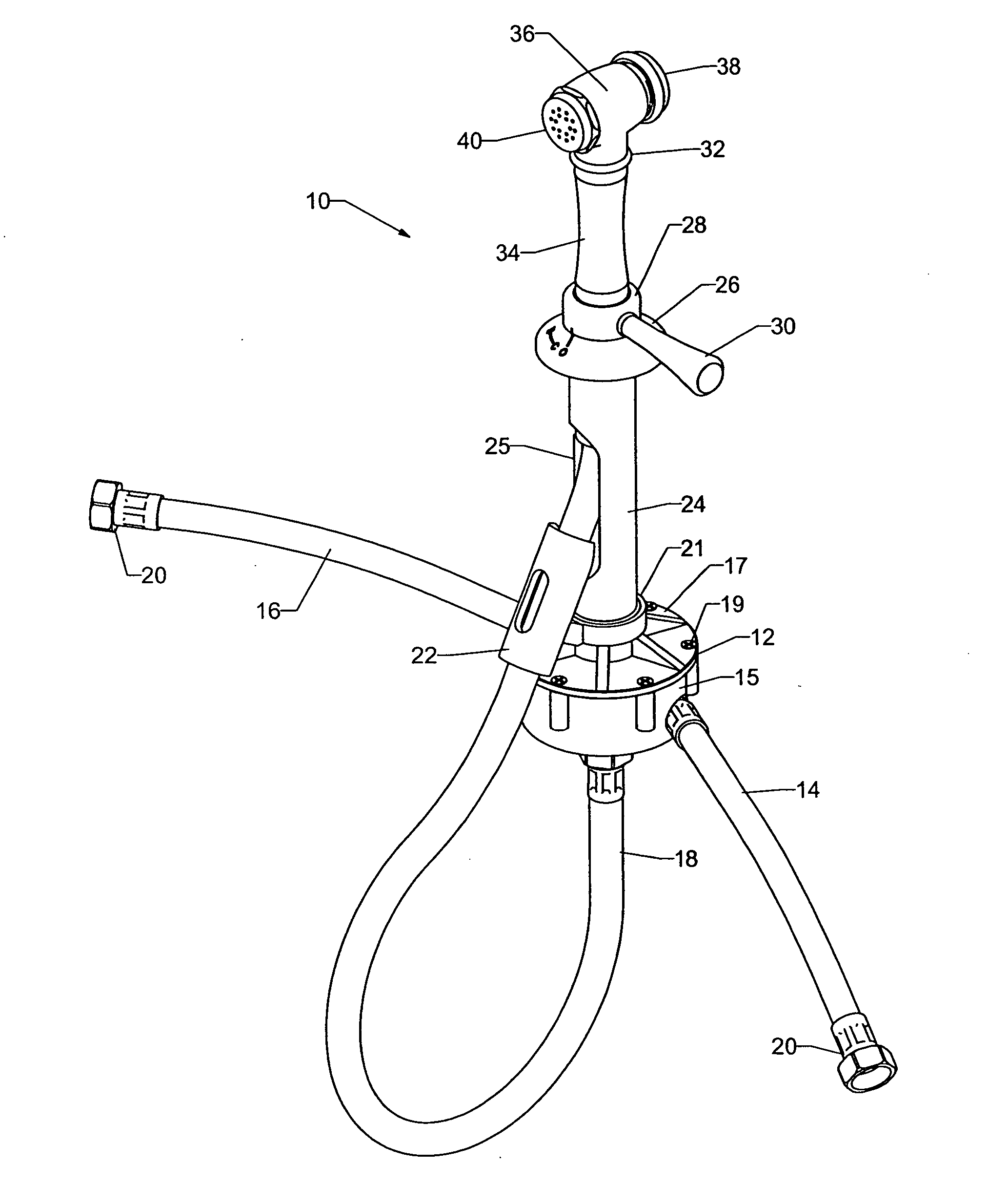
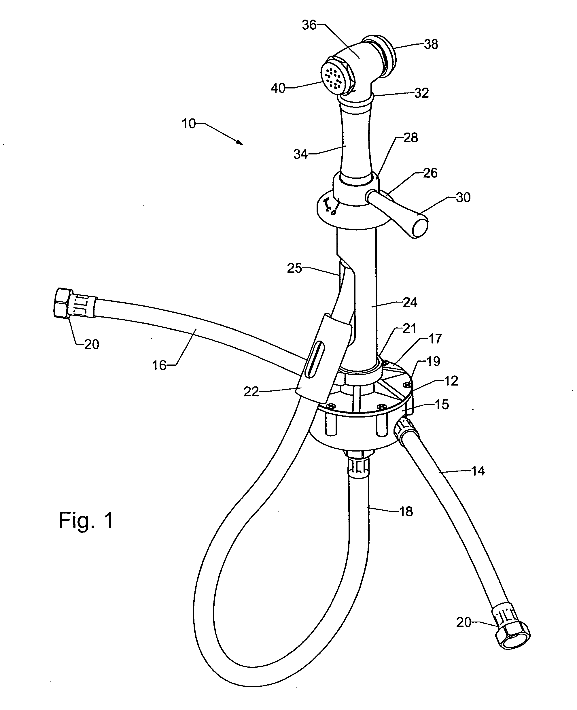
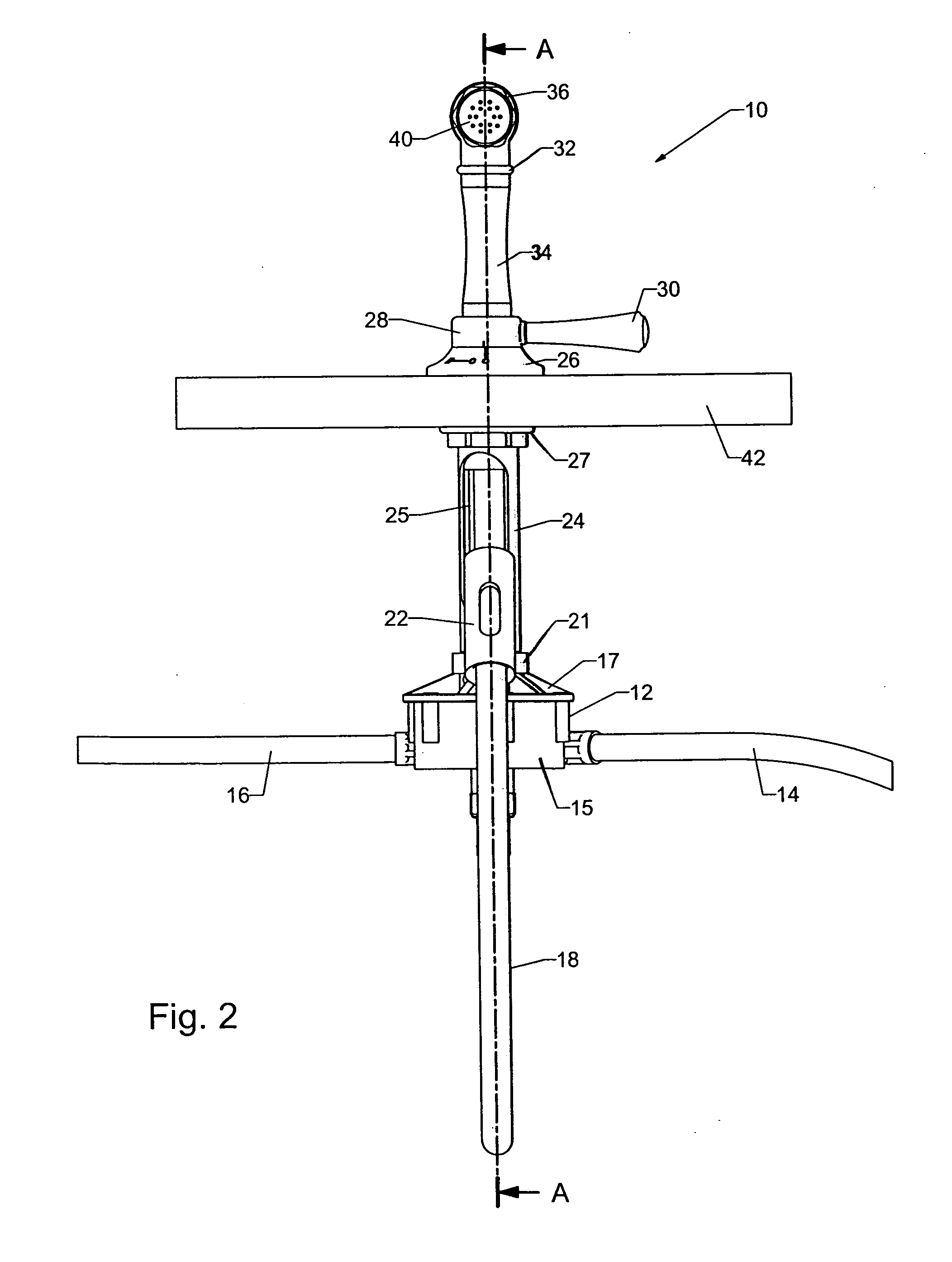
[0050]FIGS. 1 and 2 show a first hand spray device 10 which comprises two sections: a mixing chamber 12 and a spray unit 32. The mixing chamber 12 has a cylindrical body 15 with a lid 17 attached to it via screws 19 (received in corresponding recesses in the body 15). The body 15 has two input ports formed in its curved side surface; the ports are adapted to receive flexible hoses or pipes 14,16 from respective hot or cold water supplies, e.g. mains water or hot / cold water supplies to an existing household water appliance. Each pipe 14,16 has an end connector 20 for attaching to a suitable valve or supply. The body 15 has an output port formed in its bottom surface; a flexible output supply pipe 18 extends out of this port to feed water to the spray unit 32.

[0051] The spray unit 32 is removably mounted in an annular housing 26, which is connected to the mixing chamber 12 by a straight hollow tube 24. The tube 24 supports the mixing chamber 12 below the work surface. The output supp...


PUM


Abstract

A spray device for use as a supplementary fluid output, having a mixing chamber for receiving and mixing fluid from two input supplies which supplies mixed fluid to a spray head through a flexible conduit. The relative proportions of input supplies received in the mixing chamber is controlled by a mix controller having a mix actuator which is connected to a mix valve associated with the mixing chamber by an upstanding rotatable sleeve. The spray device is mounted on a hole in a work surface by mounting means. The flexible conduit and the upstanding rotatable sleeve pass through the hole in the work surface and a bore in the mounting means. The mix controller may control the rate of fluid flow through the device.

Description

BACKGROUND OF THE INVENTION [0001] 1. Field of the Invention [0002] The present invention relates to hand sprays used e.g. on kitchen sinks as alternative or additional water sources to the main tap or faucet. [0003] 2. Summary of the Prior Art [0004] Typical hand sprays (also known as side sprays) include a spray head, e.g. similar to a shower head, for delivering fluid (e.g. water) flow through a nozzle. Traditionally, the hand sprays are located next to the primary tap or taps of a kitchen sink. Side sprays are commonly used with mixer taps. The spray head typically included a hand grip to allow the user to direct the flow as desired. Some hand sprays are removably mountable on the work surface (sink holding or containing surface) and have a flexible fluid delivery hose to allow more freedom of movement. Typically, known hand sprays are operable using a simple thumb switch, which controls a valve to stop or release fluid flow through the nozzle. The thumb switch allows controlled...

Claims


Application Information

Patent Timeline
IPC IPC(8): B05B9/01B05B1/18B05B1/30B05B12/00B05B15/60B05B15/65E03C1/04
CPCB05B1/18B05B1/3046E03C2001/0415E03C1/0401E03C1/04Y10T137/86823Y10T137/86815Y10T137/9464B05B15/65B05B15/60B05B1/14B05B7/00B05B7/02B05B7/04B05B7/0408B05B9/01B05B12/00B05B12/002B05B12/14B05B1/3026F16K11/0655
Inventor HERRING, WILLIAM PETERMOORE, JAMES
Owner HORNBEAM IVY
Learn More