
Dual surge tank for vehicle cooling system

a vehicle cooling and surge tank technology, applied in vehicle heating/cooling devices, vehicle components, propulsion parts, etc., can solve the problems of increased assembly time, increased cost of fabricating and assembling two separate surge tanks, and inability to meet the requirements of vehicle cooling, so as to improve vehicle packaging and reduce overall costs

Inactive Publication Date: 2007-03-01
GM GLOBAL TECH OPERATIONS LLC
View PDF4 Cites 27 Cited by
  • Summary
  • Abstract
  • Description
  • Claims
  • Application Information

AI Technical Summary

Benefits of technology

[0008] An advantage of an embodiment of the present invention is that the dual surge tank improves vehicle packaging since package space and mounting hardware are only needed for one surge tank, rather than two, for vehicles that employ separate coolants for different portions of a cooling system. This may be particularly advantageous for hybrid vehicles that have engine coolant used with an internal combustion engine and electronics coolant used with the electronics of an electric drive system.
[0009] Another advantage of an embodiment of the present invention is that the overall costs are reduced. Only one set of tooling and one assembly step are required to provide the surge tank functions for two separate portions of a vehicle cooling system.
[0010] An additional advantage of an embodiment of the present invention is that the heat from the higher temperature engine coolant in the dual surge tank may be insulated from the lower temperature electronics coolant in the surge tank. Thus, one container provides the surge functions needed for both portions of the cooling system, while still allowing both portions of the cooling system to operate at different temperatures.

Problems solved by technology

Moreover, the cost to fabricate and assemble two separate surge tanks, as well as the assembly time needed to mount both in the vehicle, is more than is desirable.

Method used


Image

  • Dual surge tank for vehicle cooling system
  • Dual surge tank for vehicle cooling system
  • Dual surge tank for vehicle cooling system

Examples


Embodiment Construction

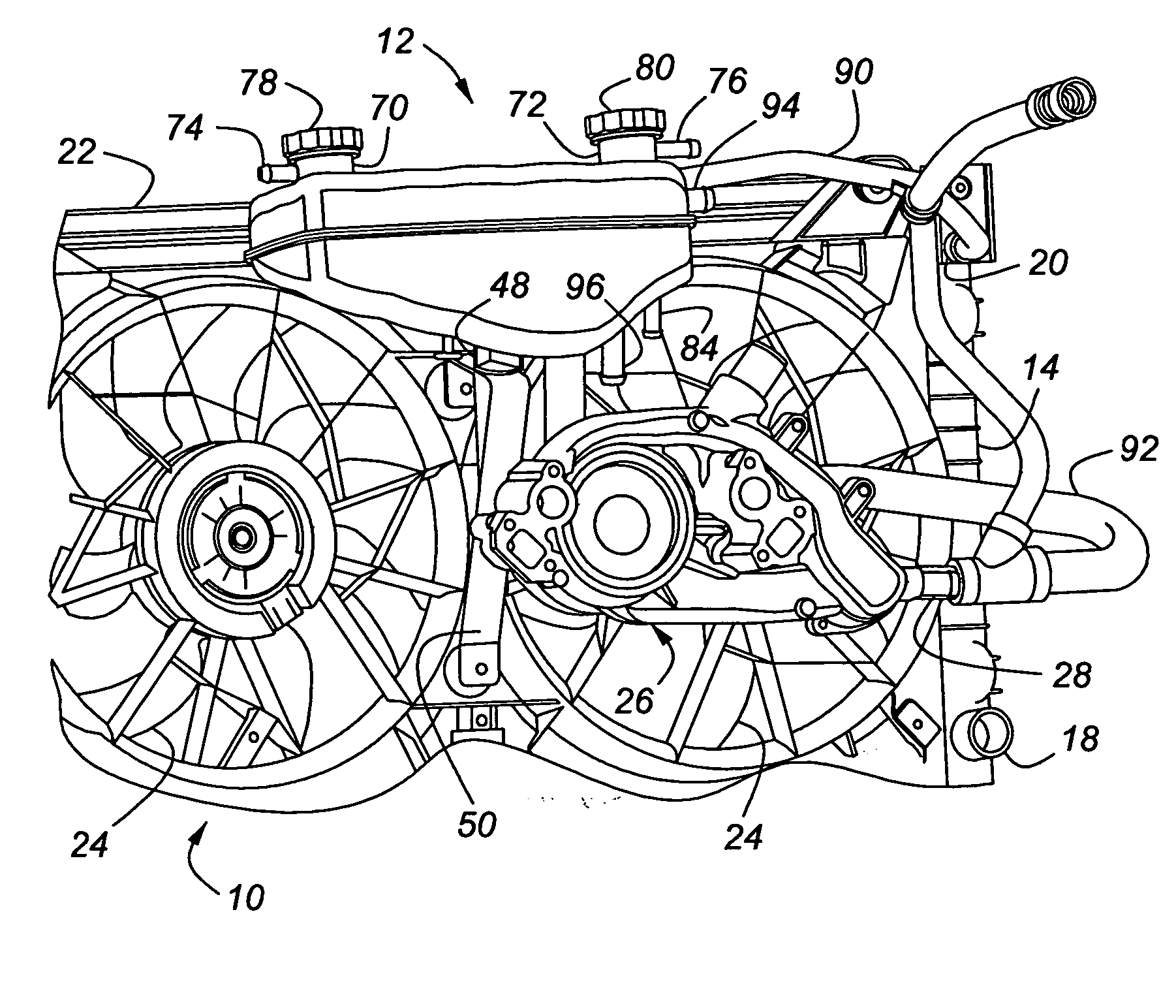
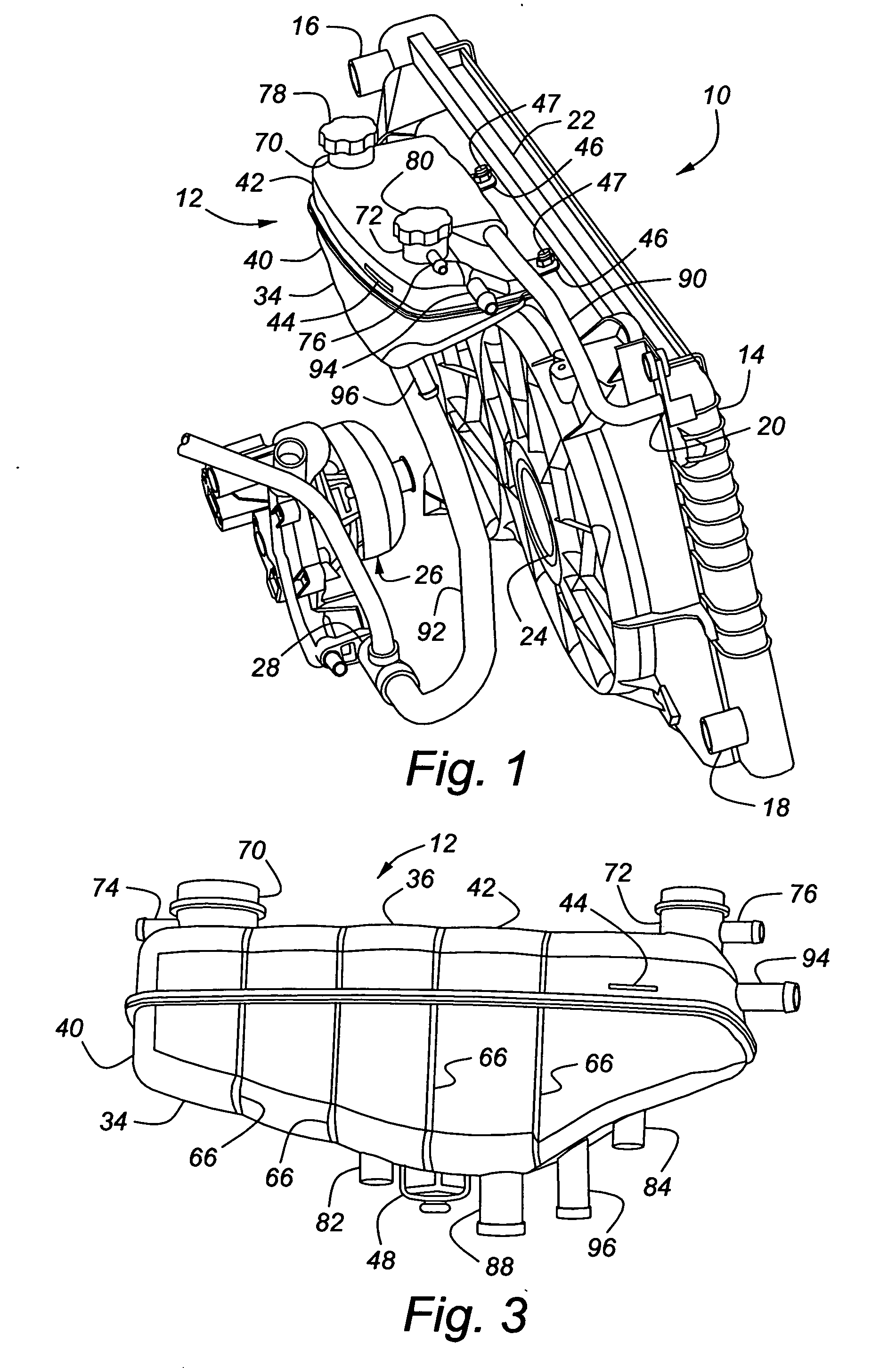
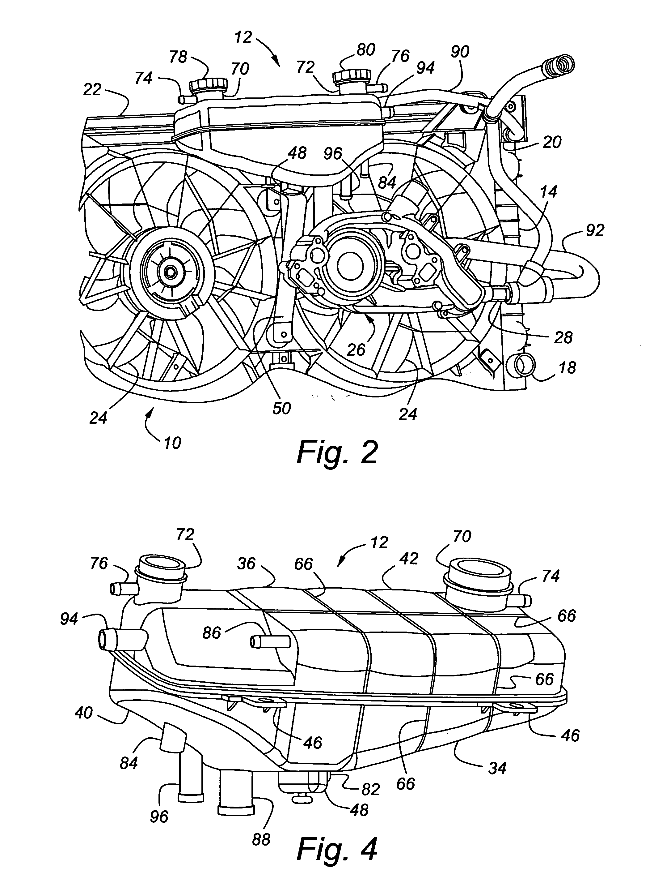
[0017]FIGS. 1-6 illustrate a cooling system for a vehicle, indicated generally at 10, that employs a dual surge tank 12. The cooling system 10 includes a radiator 14, with a coolant inlet 16, a coolant outlet 18, and an overflow port 20. Mounted adjacent to the radiator 14 is a fan shroud 22 enclosing a pair of cooling fans 24. A water pump assembly 26 for engine coolant, having an inlet 28, is preferably driven by an internal combustion engine (not shown).

[0018] The dual surge tank 12 is composed of a housing 34 having an outer wall 36 that defines a generally hollow container 38. The housing 34 may be formed of a clamshell shaped lower portion 40 and a clamshell shaped upper portion 42. The housing 34 may be made of, for example, a polycarbonate—although other suitable materials may be used instead, if so desired. A fluid level line 44 (shown in FIGS. 1 and 3) may be molded into or marked on the outside of the dual surge tank 12. A second fluid level line (not shown) may also be ...


PUM


Abstract

The invention concerns a dual surge tank for use in a cooling system of a vehicle. The dual surge tank includes a housing having an outer wall defining a container, and a divider, located within the housing, dividing the container into a first chamber adapted to contain a first liquid and a second chamber adapted to contain a second liquid, with the divider sealing the first chamber from the second chamber. The divider may provide heat insulation between the two chambers. The first chamber may contain engine coolant and the second chamber may contain electronics coolant.

Description

BACKGROUND OF INVENTION [0001] The present invention relates generally to a cooling system for a vehicle, and in particular to a surge tank employable with vehicle cooling systems. [0002] Conventional vehicles powered by internal combustion engines typically have an engine cooling system that uses a liquid (usually a mixture of water and antifreeze) to maintain the engine within a desired range of operating temperatures. The conventional cooling systems include a radiator for cooling the liquid and a water pump for moving the liquid through the engine and back to the radiator. These cooling systems also typically employ a surge tank (also called a reservoir or an expansion tank) that operates in conjunction with the radiator. The surge tank provides a container for retaining overflow of the engine coolant due to expansion of the coolant as it heats up, and allowing engine coolant to return when coolant in the radiator cools. This is accomplished by allowing positive and vacuum press...

Claims


Application Information

Patent Timeline
IPC IPC(8): B60H1/00
CPCB60K11/02
Inventor FARLEY, MARY L.
Owner GM GLOBAL TECH OPERATIONS LLC
Learn More