
Heating system for a portable carpet extractor

Inactive Publication Date: 2007-03-01
TACONY A MISSOURI
View PDF23 Cites 14 Cited by
  • Summary
  • Abstract
  • Description
  • Claims
  • Application Information

AI Technical Summary

Benefits of technology

[0016] Therefore, an extractor apparatus which overcomes many of the perceived shortcomings of the prior art devices and practices is the subject matter of the present application. The portable extractor includes a wheel mounted base having at least a solution tank for dispensing and recovering cleaning solution. In one embodiment of the invention, a cleaning wand connected to the solution tank by pliable hosing, the cleaning wand having a cleaning head which contacts the surface to the cleaned for dispensing and recovering cleaning solution. A fluid pump circulates cleaning solution in a path between the solution tank and the cleaning head of the wand. A vacuum motor comprises a vacuum source for the extractor apparatus, the vacuum source being in communication with the cleaning head of the wand for suctioning the surface being cleaned. The vacuum motor is mounted on the b

Problems solved by technology

The heat generated by these motors has, in the past, been simply exhausted and in a sense wasted.
Because the available electrical outlet capability is necessarily limited in typical residential and commercial buildings in North America, compromises in temperature rise and / or fluid flow rate must necessarily be made.
Sometimes, the increased amperage being drawn has caused the operator to blow electrical fuses in the structure being cleaned.
In many cases, it is also not generally practical to utilize multiple electrical cords running to the extractor unit.
As a result, one smaller cord may overheat due to the increased electrical load.
While cleaning devices having self contained power sources have operated with some degree of success, the useful operational time of such devices is quite limited.
Still further, machines of this type which have rechargeable batteries are also relatively large and heavy, and can be difficult to maneuver in small spaces.

Method used


Image

  • Heating system for a portable carpet extractor
  • Heating system for a portable carpet extractor
  • Heating system for a portable carpet extractor

Examples


Embodiment Construction

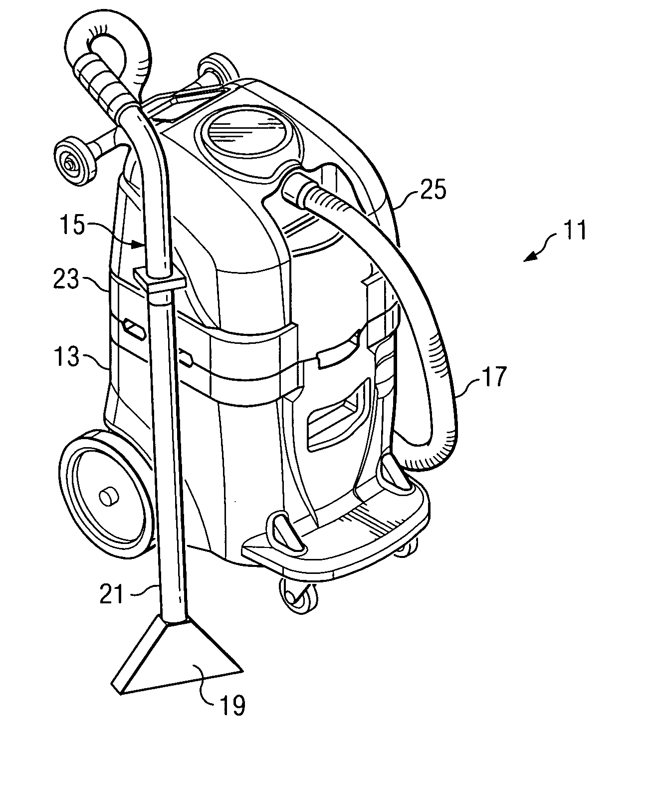
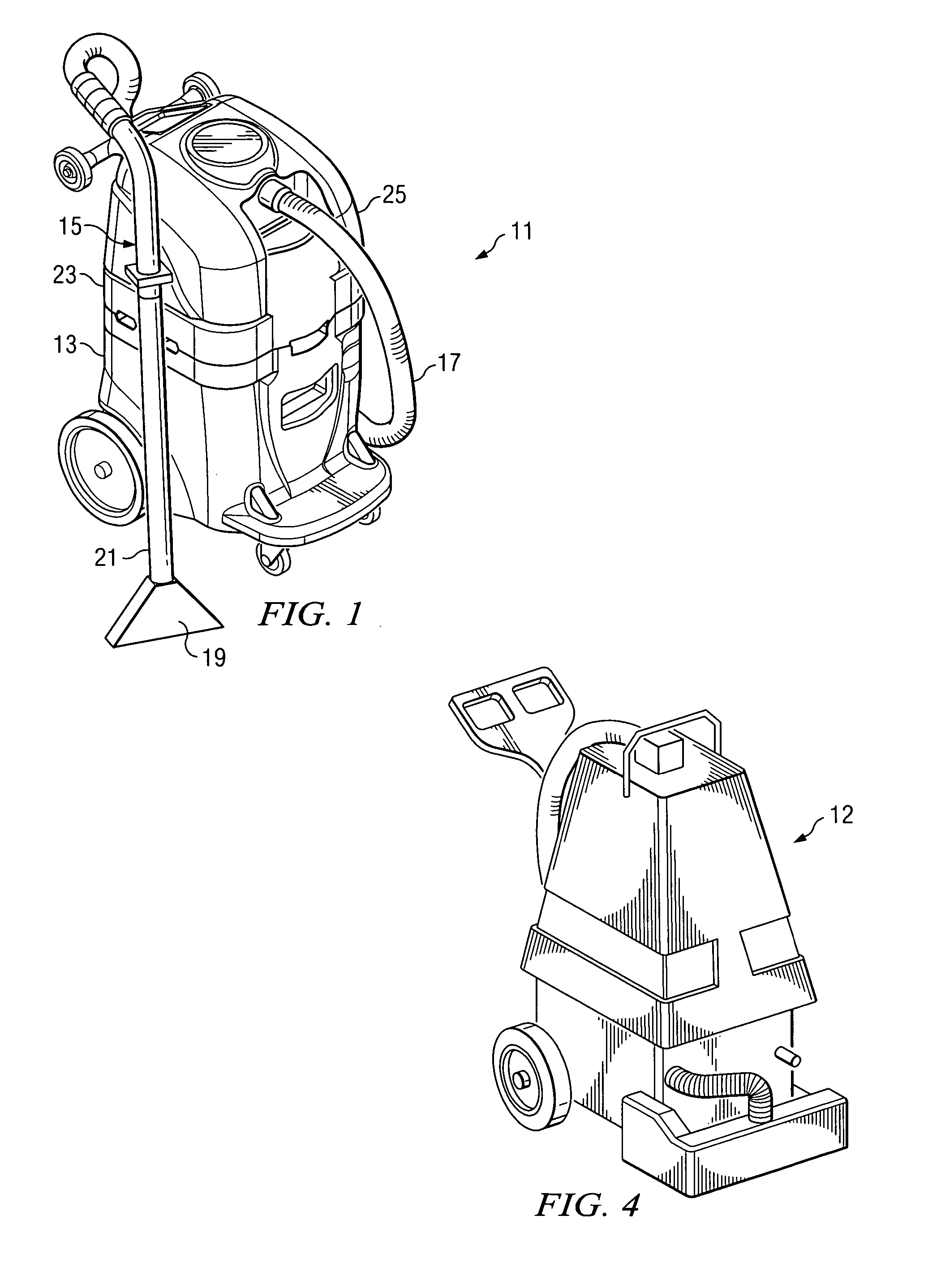
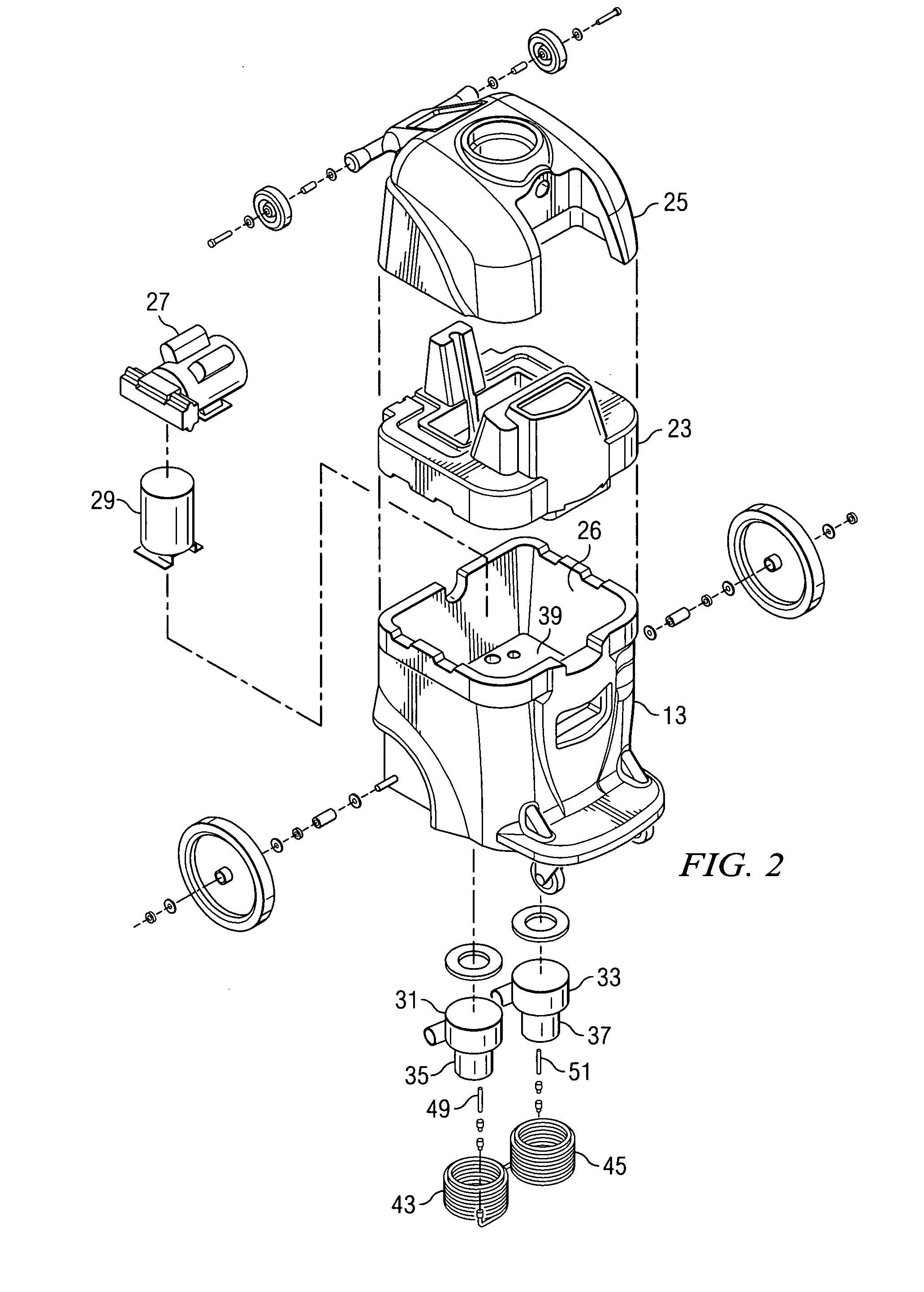
[0024] Turning to FIG. 1, there is shown an apparatus for cleaning a planar covered surface of the invention designated generally as 11. The surface to be cleaned can be, for example, a carpeted surface, a wall covering, upholstery, or the like. In the first embodiment of the invention illustrated in FIG. 1, the apparatus 11 is a carpet extractor of the type used to remove soil from the carpeted surface which features a cleaning head carried on a wand and an interconnecting length of flexible hosing which connects the wand to the base unit. With reference briefly to FIG. 4, another type carpet extractor is shown which features an integrally mounted cleaning head (12 in FIG. 4) which moves across the floor surface as the machine itself is moved back and forth. As will be apparent in the description which follows, the improved heating system of the invention can be used with either an extractor of the type shown in FIG. 1, or with the extractor shown in FIG. 4. However, for simplicity...


PUM


Abstract

A portable extractor apparatus is shown which includes a wheel mounted base having a solution tank for dispensing and recovering cleaning solution. A cleaning wand is connected to the solution tank and has a head which contacts the surface to the cleaned for dispensing and recovering cleaning solution. A fluid pump circulates cleaning solution in a path between the solution tank and the cleaning head. A vacuum motor provides a vacuum source for the cleaning head for suctioning the surface being cleaned and has an exhaust fan for exhausting excess heat created by the operation of the vacuum motor. A fluid operated heat exchanger is mounted in the vicinity of the vacuum motor. The heat exchanger is plumbed in the circulation path of the cleaning fluid, whereby excess heat generated by the vacuum motor is transferred to the cleaning fluid being applied from the cleaning head onto the surface to be cleaned. The cleaning head can also be integrally mounted on the wheel mounted base.

Description

BACKGROUND OF THE INVENTION [0001] 1. Field of the Invention [0002] The present invention relates to a portable machine for cleaning planar surfaces, such as carpeted floors, upholstery, wall coverings and the like, and finds particular application in such machines where hot cleaning liquids are sprayed onto the surface and are then removed by suction. [0003] 2. Description of the Prior Art [0004] Cleaning systems that circulate and spray liquids are widely used for cleaning carpets, upholstery, fabric and wall coverings, as well as for hard surfaces such as ceramics. Cleaning systems of this type which circulate and spray liquids often include a solution tank of liquid cleaning solution supported on a wheel mounted base or framework. The framework also supports a liquid pump for circulating the cleaning solution and one or more vacuum motors for recovering the solution and returning the used solution to a recovery tank. Many of these systems use a “cleaning head” which is part of a...

Claims


Application Information

Patent Timeline
IPC IPC(8): A47L11/30
CPCA47L11/34A47L11/4086
Inventor DAY, H.
Owner TACONY A MISSOURI
Learn More