Callus elongating/regenerating device
a callus elongation and regenerative technology, applied in the field of callus elongation/regenerative devices, can solve the problems of inconvenient daily life, inconvenient placement of the device, and insufficient biocompatibility of the replacement device with the subject body
- Summary
- Abstract
- Description
- Claims
- Application Information
AI Technical Summary
Benefits of technology
Problems solved by technology
Method used
Image
Examples
second embodiment
of the Invention
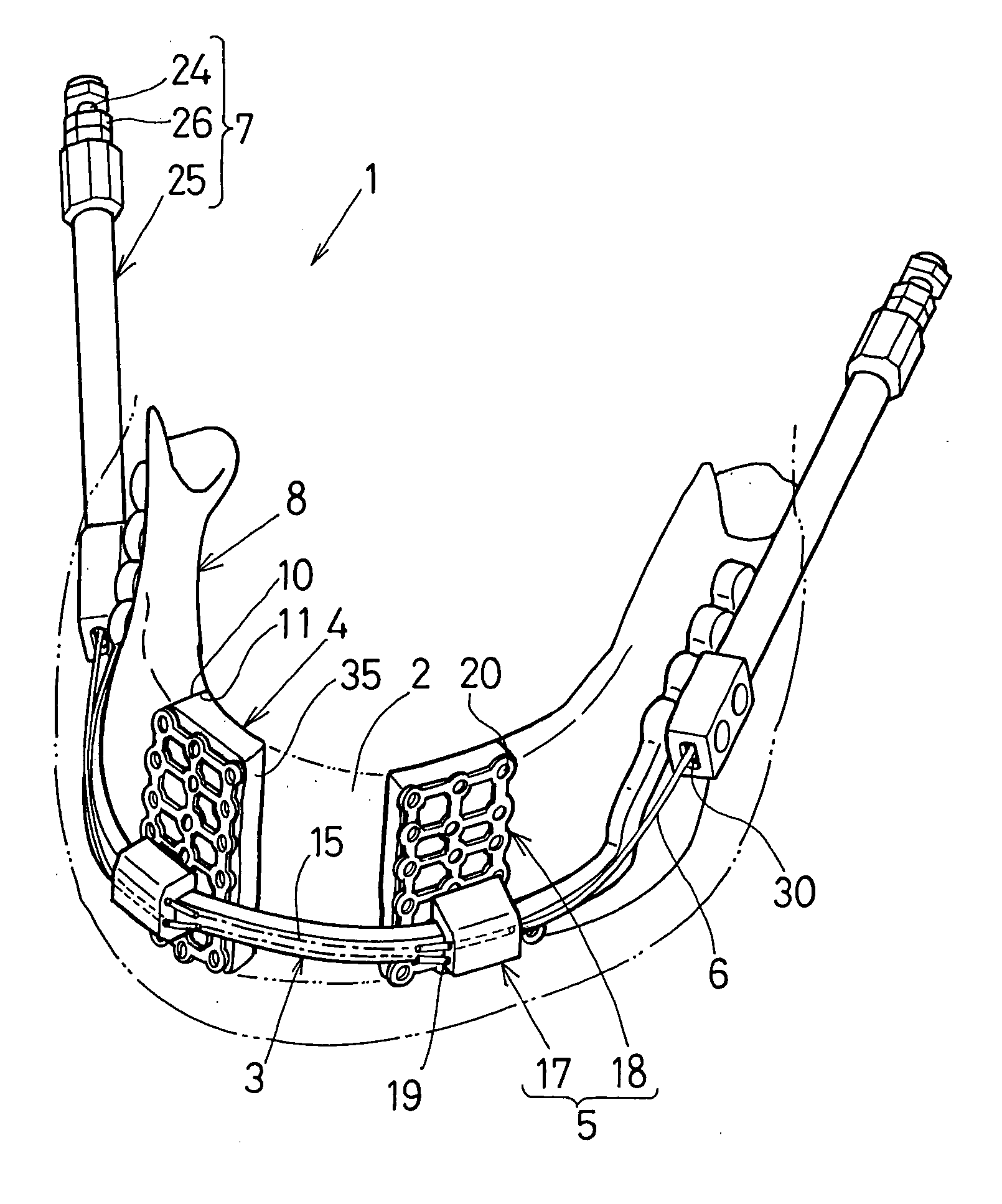
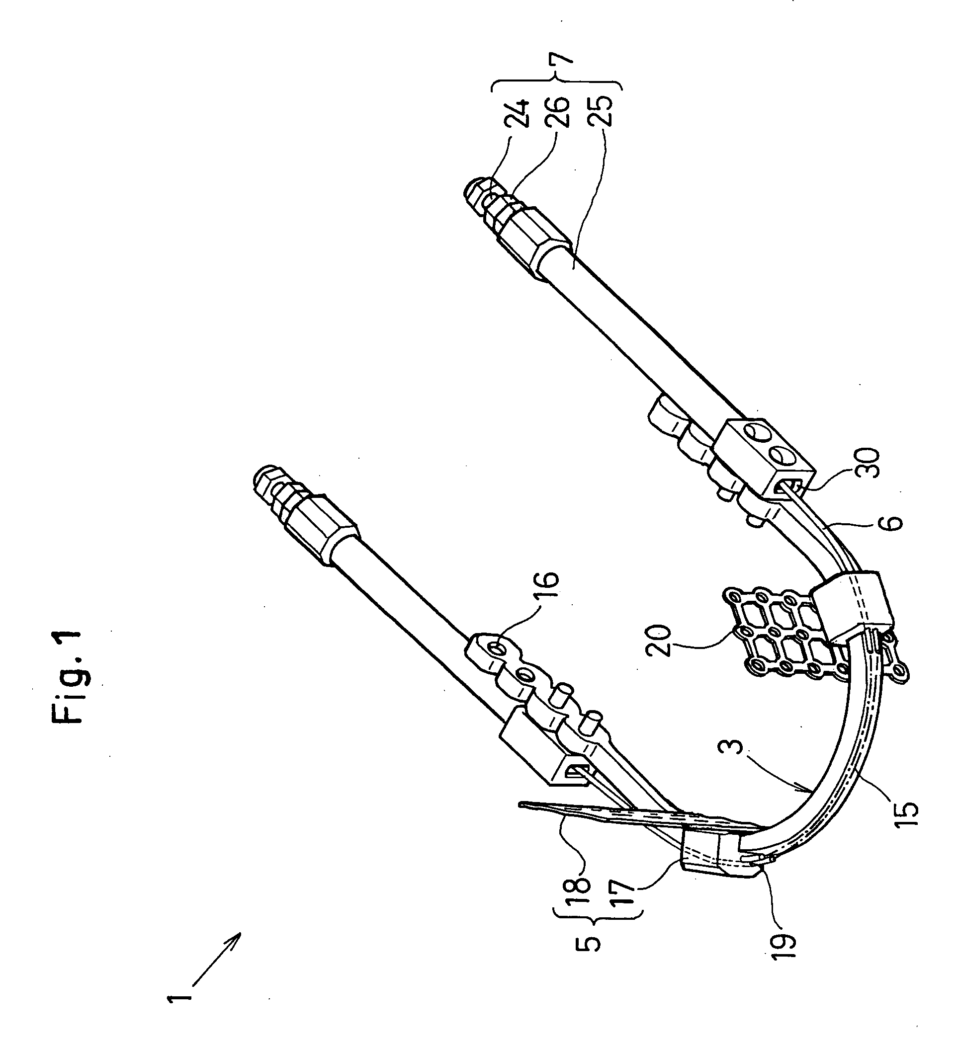
[0103]FIGS. 10 and 12 show a second embodiment of the invention in which a cap nut 39 is provided at the rear end of the rod 24 in the operating member 7. The flat surface 27 of the rod 24 has a lengthwise groove 40 to accommodate the wire 6. The groove 40 extends along the full length of the one flat surface 27 to a part of the other flat surface 27 via the rear end tip of the rod 24. This holds the wire 6 in its axial direction within a hollow space 29 between an inner wall of the sleeve 25 and an outer wall of the rod 24.
[0104] In this instance, the cap nut 39 removably secures the halfway portion of the wire 6 bent along the rear end tip of the rod 24.
Advantages of the Invention
[0105] With the wire 6 held within the hollow space 29 of the sleeve 25 so as to removably engage against the rear end tip of the rod 24 by means of the cap nut 39, it is possible to insure an easy connection and disconnection between the wire 6 and the rod 24, while at the same time, r...
third embodiment
of the Invention
[0108]FIGS. 13 and 14 show a third embodiment of the invention in which a stress concentration portion 42 is provided on the sleeve 25 so that a concentrated stress develops at the stress concentration portion 42 when a bending moment is applied to the sleeve 25. The stress concentration portion 42 is formed as a notched portion at the side of the sleeve 25 in which the exit opening 30 resides.
[0109] The notched portion is formed by cutting an outer surface of the sleeve 25 in the manner to expose a notched side to a portion opposite to the plate 3. With the use of the well known bender tool, it is possible to bent the sleeve 25 at the the stress concentration portion 42 in such a direction as moving away from the plate 3.
Advantages of the Invention
[0110] Such is the structure that it preferentially bends the sleeve 25 at the stress concentration portion 42 to avoid the operating member 7 from three-dimensionally interferring with other part of the body.
fourth embodiment
of the Invention
[0111]FIG. 15 show a fourth embodiment of the invention in which a graduated portion 44 is provided with the rod 24 in order to indicate its lengthwise dimension when the rod 24 is protracted out of the sleeve 25
Advantages of the Invention
[0112] With the graduated portion 44 thus provided, it is possible to visually recognize how far the bracket 5 is pulled by the tractive force of the wire 6 (i.e., a displacement of the bracket). This enables the operator to readily measure how far the callus 9 is osteoplastically extended (i.e., an extension of the callus).
PUM
 Abstract
Description
Claims
Application Information
 - R&D
- Intellectual Property
- Life Sciences
- Materials
- Tech Scout
- Unparalleled Data Quality
- Higher Quality Content
- 60% Fewer Hallucinations
Browse by: Latest US Patents, China's latest patents, Technical Efficacy Thesaurus, Application Domain, Technology Topic, Popular Technical Reports.
© 2025 PatSnap. All rights reserved.Legal|Privacy policy|Modern Slavery Act Transparency Statement|Sitemap|About US| Contact US: help@patsnap.com


